ST-SP Pag. 51 Rev 02 05/13
UK
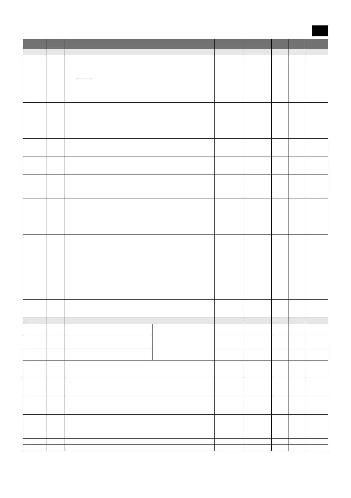
Code Level Descr. Range Unit MBP LBP HBP
List of -dEF defrosting parameters
dtY* 1 Defrosting type
0 = heating element: ends at temperature or after maximum safe time
(timeout)
1 = hot gas
: ends at temperature or after maximum safe time
(timeout)
For defrosting using a heating element, there is a 1 second delay
between the compressor switching off and the defrosting relay being
triggered
0,1 1 1 0
dit 1 Defrosting interval
The maximum time (from start to start) between two consecutive
defrosting cycles. When this time expires, a defrosting cycle is enabled
(cyclical defrosting). The timer is reset at each defrosting request (even
if not cyclical).
0 = cyclical defrosting disabled
0 … 250 h 6 6 6
dct 1 Defrosting interval count mode
0 = counts if the compressor is operating
1 = counts all the time
0,1 1 1 1
dOH 1 Defrosting start delay at power-on
The time, as from when the instrument is switched on, for which any
defrosting requests are frozen (manual defrosting excluded)
0 … 250 min 0 0 0
dEt* 1 Defrosting timeout
When the set time expires, defrosting is in any case ended, even if the
defrost end temperature has not been reached, passing on to the drip
phase
1 … 250 min 15 15 15
dSt* 1 Defrost end temperature
The probe 2 temperature above which defrosting is ended. If, at the
start of a defrosting cycle, the temperature is greater than that set, no
defrosting will be carried out. In the event of a probe 2 malfunction,
the defrosting cycle will in any case terminate after reaching a time
limit
-50.0 …
199.0
°C [°F] 10 15 10
dS2 1 Defrost end temperature for the second evaporator
The probe 3 temperature above which defrosting for the second
evaporator is ended. If, at the start of a defrosting cycle, the
temperature is greater than that set, no defrosting will be carried out.
In the event of a probe 3 malfunction, the defrosting cycle will in any
case terminate after reaching a time limit.
This function is only enabled if P01=3o4, Co4=3 and CP0=2 (alarm
relay used for second evaporator defrosting and probe 3 used to
detect the temperature of the second evaporator). In this case, the
dripping phase will begin after the defrosting cycles of both
evaporators have ended.
-50.0 …
199.0
°C [°F] 10 10 10
dPO 1 Defrosting at power-on
0 = disabled
1 = defrosting when the instrument is switched on
0,1 flag 0 0 0
List of -FAn fan parameters
FSt 1 Fans switch on temperature probe2 ≥ FSt: fans off
Fot ≤ probe2 < (FSt –
FAd): fans on
probe2 < (Fot – FAd): fans
off
-50.0 …
199.0
°C [°F] 8 -5 50
Fot 1 Fans switch off temperature
-50.0 …
199.0
°C [°F] -50 -50 -50
FAd 1 Fans switch on and off differential 1.0 …
90.0
°C [°F] 2 2 2
Fdt 1 Post-dripping time
The time after the dripping phase, during which the fans remain
switched off
0 … 60 min 1 2 0
dt 1 Dripping time
The time after a defrosting cycle during which the compressor and the
evaporator are stopped in order to favour evaporator dripping
0 … 60 min 2 2 0
dFd 1 Fans deactivated during defrosting
0 = fans activated (operation set from FPt)
1 = fans deactivated
0,1 flag 1 1 0
FCO 1 Fans activated with compressor off
0 = fans deactivated
1 = fans activated (operation set from FPt)
2 = fans in duty cycle operation
0 … 2 0 0 0
Fon 1 Fans ON time during duty cycle operation (FCO=2) 1 … 60 min 15 15 15
FoF 1 Fans OFF time during duty cycle operation (FCO=2) 1 … 60 min 15 15 15
 Loading...