6. PROGRAM CONTROL
IMR02L04-E3
6-13
Wait release trigger selection [
Parameter setting mode: Wait memory group setting block
]
Select Wait release method.
Set “1” at the one place to conduct Zone wait function (Wait releasing by Wait zone judgment).
When using Digital input (DI) in combination with Zone wait function, also set “1” at hundred places.
Parameter symbol Data range Factory set value
RE.TRG
00000
Zone wait 1 (the controller) [0: Invalidate, 1: Validate]
Zone wait 2 (all slave controllers) [0: Invalidate, 1: Validate]
Wait release by digital input (DI) [0: Invalidate, 1: Validate]
Unused
00001
The ten places is for slave controller of the Intercontroller communication.
Wait time-out set value [Parameter setting mode: Wait memory group setting block]
Set duration of Time-out for wait release by Time-out.
Parameter symbol Data range Factory set value
TM.oUT
From 0:00 to 500:00 (Hour: Minute), or
from 0:00 to 500:00 (Minute: Second)
0:00 (Hour: Minute or Minute: Second): Unused
0 hour 00 minute
Set time unit at F80.05 in the Engineering mode. Refer to 4.5.5 Engineering mode (P. 4-43).
Parameter setting to set Wait function by segment
Digital input (DI) assignment [Engineering mode F23.01]
Assign Digital input (DI).
Set 2, 3 or 4 to set wait function for each segment.
Parameter symbol Data range Factory set value
DISL
0 to 5 (For details, refer to DI Assignment Code Table) 0
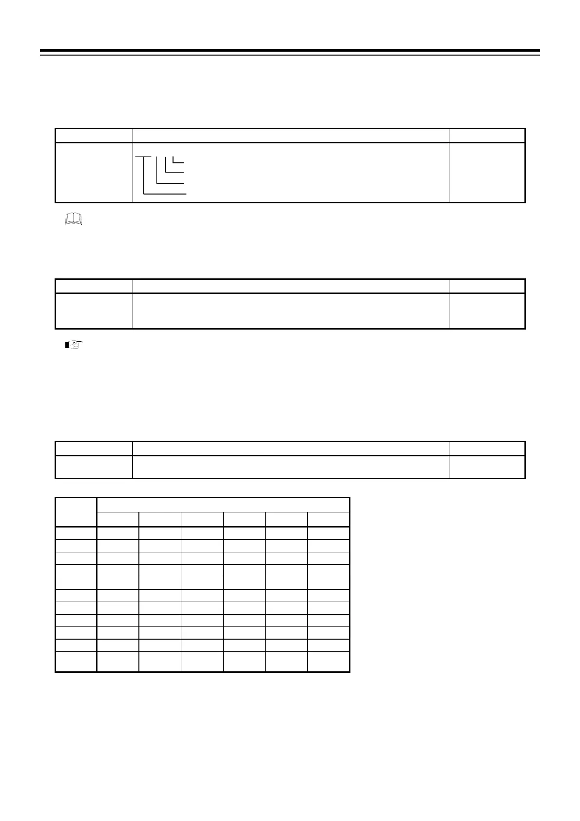
DI Assignment Code Table
DI
number
Set value
0
a
1
a
2 3
b
4 5
DI1 PTN1 PTN1 WAIT WAIT WAIT WAIT
PTN1, 2, 4, 8, 16, 32, 64:
DI2 PTN2 PTN2 WAIT WAIT WAIT WAIT Pattern number switch
DI3 PTN4 PTN4 WAIT WAIT WAIT WAIT
P. SET: Pattern set
DI4 PTN8 PTN8 WAIT WAIT WAIT WAIT
WAIT: Wait state release
DI5 PTN16 PTN16 WAIT WAIT WAIT WAIT
RESET: Reset mode (RESET) setting
DI6 P. SET P. SET WAIT WAIT WAIT WAIT
RUN: Program control mode (RUN) setting
DI7 RESET RESET PTN1 PTN1 RESET RESET
STEP: Step (STEP) function
DI8 RUN RUN PTN2 PTN2 RUN RUN
HOLD: Hold (HOLD) function
DI9 STEP STEP PTN4 PTN4 STEP STEP
Direct/Reverse:
DI10 HOLD PTN32 PTN8 PTN8 HOLD HOLD Direct/Reverse action switching
DI11 PTN32 PTN64 P. SET PTN16
Direct
Reverse
PTN_INC
PNT_INC:
Pattern increment
a
Setting zero (0) or “1” is suitable when DI1 to DI6 (optional) are specified at ordering.
b
When selecting set value 3, the set value of the Pattern input method of Digital input (DI) (P. 4-35) should be changed to 1 or 3.
[Refer to the PF900/PF901 Instruction Manual (IMR02L03-E) on the CD-ROM.]
 Loading...