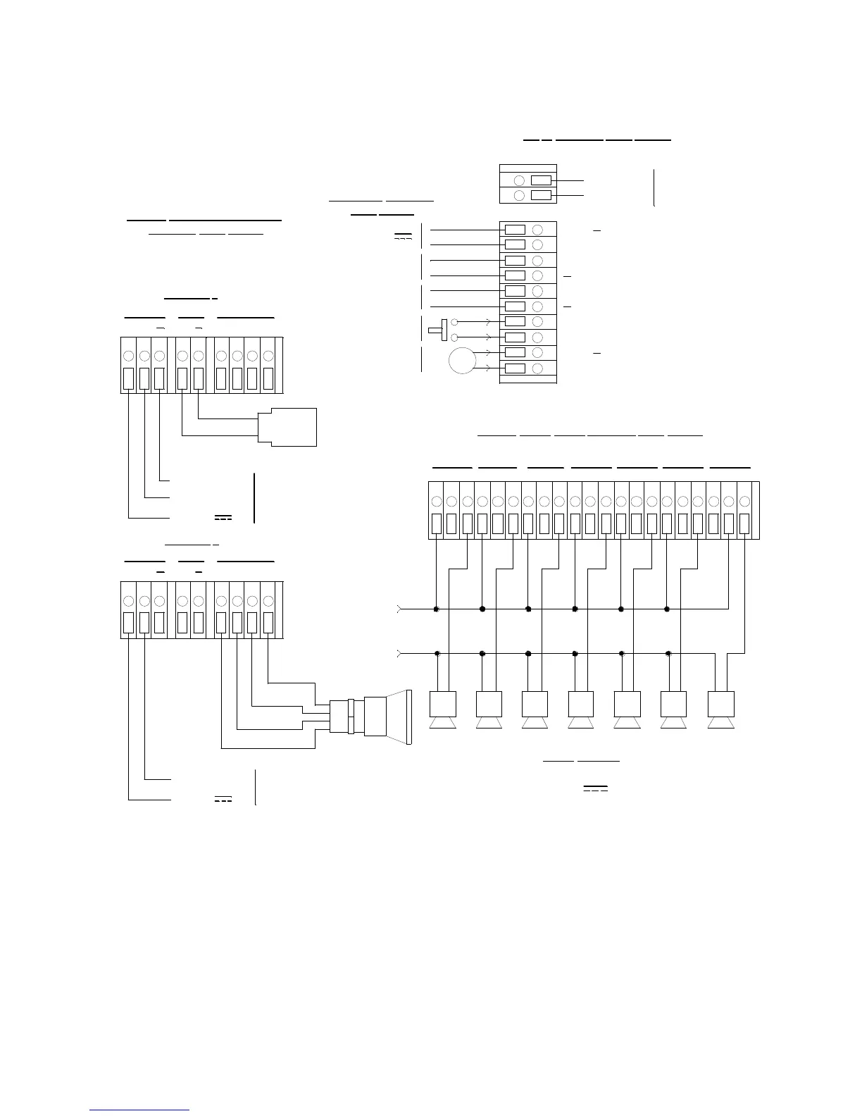
NOTE: AC ground
connection is m ade
to ground stud in
lower right corne r
of circuit board.
115V/220V~
+
COM-A1 COM-FAILCOM-A2
BAT
CH2-A1CH1-A2
Reset Switch
(Fa ctor y W ire d)
Buzzer
(Fa ctor y W ire d)
Oxygen
Detector
Channel 1 Recorder
1K MaxImpedance
BUZ
Green
+
White
+S
LEL
O XYG ENAM P /P REAM P
NO NC C NO NC CNO NC CNO NC C NO NC C
CHANNEL 2
+S +
LEL
O XYG ENAM P /P REAM P
Typical Detector/Transmitter
Terminal StripWiring
Only one detector or t ransmitter canbe
wired to Ch1 orCh2 ata time. See detector
head wiring diagram for specific wiring.
BUZ +
RESET
RESET
CH2-A2
Typical Alarm Relay TerminalStrip Wiring
BAT +
AC
In TerminalStrip Wiring
CH1
OUT
Line (Hot)
Neutral
Black
LEL Detector
Contact Rating of 10 Ampsat 115/220V~
Resistive or 10A @ 30V Resistive for E ach
SetofAlarmRelayContacts.
NO NC C
RW G B
Green
FB ( 4-20 m A)
2-W ire 4-20ma
Transmitter
+24V
3-W ire 4-20ma
Transmitter
- DC GROUND
FB ( 4-20 m A)
RW GB
+24V
Alarm Devices
Channel 2 Recorder
1K MaxImpedance
CHANNEL 1
CH2
OUT
+
White
Red
NO NC C
Controller Terminal
Strip Wiring
24 V
CH1-A1
4- 20mAOut
4- 20mAOut
Alarm Device
Power
 Loading...