Rhein-Nadel Automation GmbH 9
VT-BA-ESR-ESM3000-EN_2021.docx / 15 March 2021
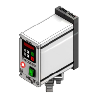
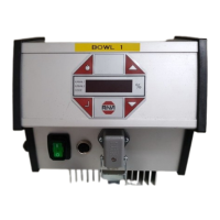
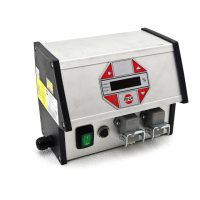
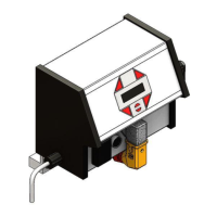
The devices are available as stand-alone add-on units or as cabinet-mounting units.
• Power switch
• Control and display panel
• Mains connection cable with grounding-type plug.
• Output socket-outlet for connection of feeder.
Sensor socket-outlet. Standard configuration includes 24 V DC sensors with PNP output.
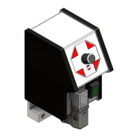
• Control and display panel
• Electrical connection to terminals
• Screw fastening for mounting plate
240 V +/- 10 %, 50/60 Hz
110 V +/- 10 %, 50/60 Hz
0...205 V at 240V
0...95 V at 110V
Recommended *
backup protection:
16 A time-lag
min. circuit-breaker tripping characteristic ‘D’
24 V DC (10-24VDC) or floating contact with internal ref. 24 VDC
Changeover contact 250V, 1 A
Soft start delay, soft
stop delay:
0 ... 60 sec. separately adjustable
0 ... 10V DC, 0(4) … 20mA
1 sensor input for PNP sensor
0 ... 60 sec. separately adjustable
0 ... 60 sec. separately adjustable
Relay 1, floating changeover contact 1A, 250 VAC, 60 VDC
24VDC, 50mA, (PNP), short-circuit-proof
1000 m 0.5 % nominal current reduction per every additional 100 m
The devices are equipped with starting current damping. However, a charging current peak may occur due
to the internal capacitors condensers if several devices are powered on at the same time. Upstream fuses
or min. circuit-breakers should therefore be time-delayed.
In order to ensure the efficiency of the internal starting current damping, a waiting time of 5 seconds has to
be observed after switching off the operating voltage until switching it on again.
3.2. Cabinet-mounted device
 Loading...