Do you have a question about the RNA ESK 2001 and is the answer not in the manual?
Covers design, fundamental safety directives, and qualifications for personnel operating equipment.
Details on intended use, device hazards, protection of drive system, and degree of protection.
Characteristic features, applicable directives/standards, and detailed technical specifications.
List of available accessories with their RNA article codes for connectors and adapters.
Pre-operation checks, operating modes (half-wave, full-wave), and automatic mode change.
Sensor input configurations, linkages, and status outputs/relays functionality.
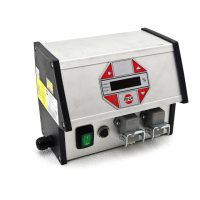
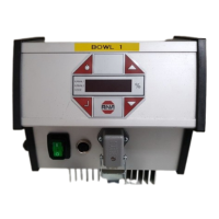
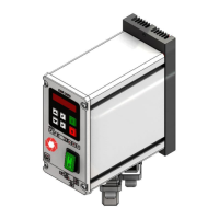
General operation, controller display, keypad, and starting-up procedures.
Navigating the main menu for setpoint entry and display for channels 1 and 2.
Overview of individual codes for controller programming, detailing their functions.
Configuring channels, sealing setpoints, activating/linking sensor inputs.
Cycle monitoring, logic configurations, and checking controller operational status.
Inhibiting settings, external voltage control, saving, and retrieving parameters.
List of error messages, their causes, and reset procedures for the controller.
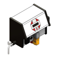
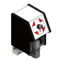
Detailed physical dimensions and layout of the controller unit.
Electrical wiring diagram showing all connections for power, drives, sensors, and outputs.
| Brand | RNA |
|---|---|
| Model | ESK 2001 |
| Category | Controller |
| Language | English |