Rhein-Nadel Automation GmbH 10
VT-BA-ESK2001_EN_2023.docxVT-BA-ESK2001_EN_2023.docx
The status outputs are used for remote diagnostics of the controller status or of the links of several controllers
with one another.
They are designed as freely available NPN-doped transistor circuits and they are floating.
With the status output READY the transistor circuit is switched through whenever the controller is connected
to power supply and switched on by its power switch closed.
The status output ACTIVE requires the same conditions for switching-through as "READY". In addition, chan-
nel 1 must be operating actively, the transistor blocks in case of ACCUMULATION, OFF or STOP. The status
outputs as well as the external enabling inputs are to be wired via plug connector XS4.
The two relays have different functions. K1 operates as a status relay parallel to the ACTIVE status output.
K2 serves either for a blowing air switch-off delay (4 sec.) or for cycle monitoring of one of the two sensor
channels.
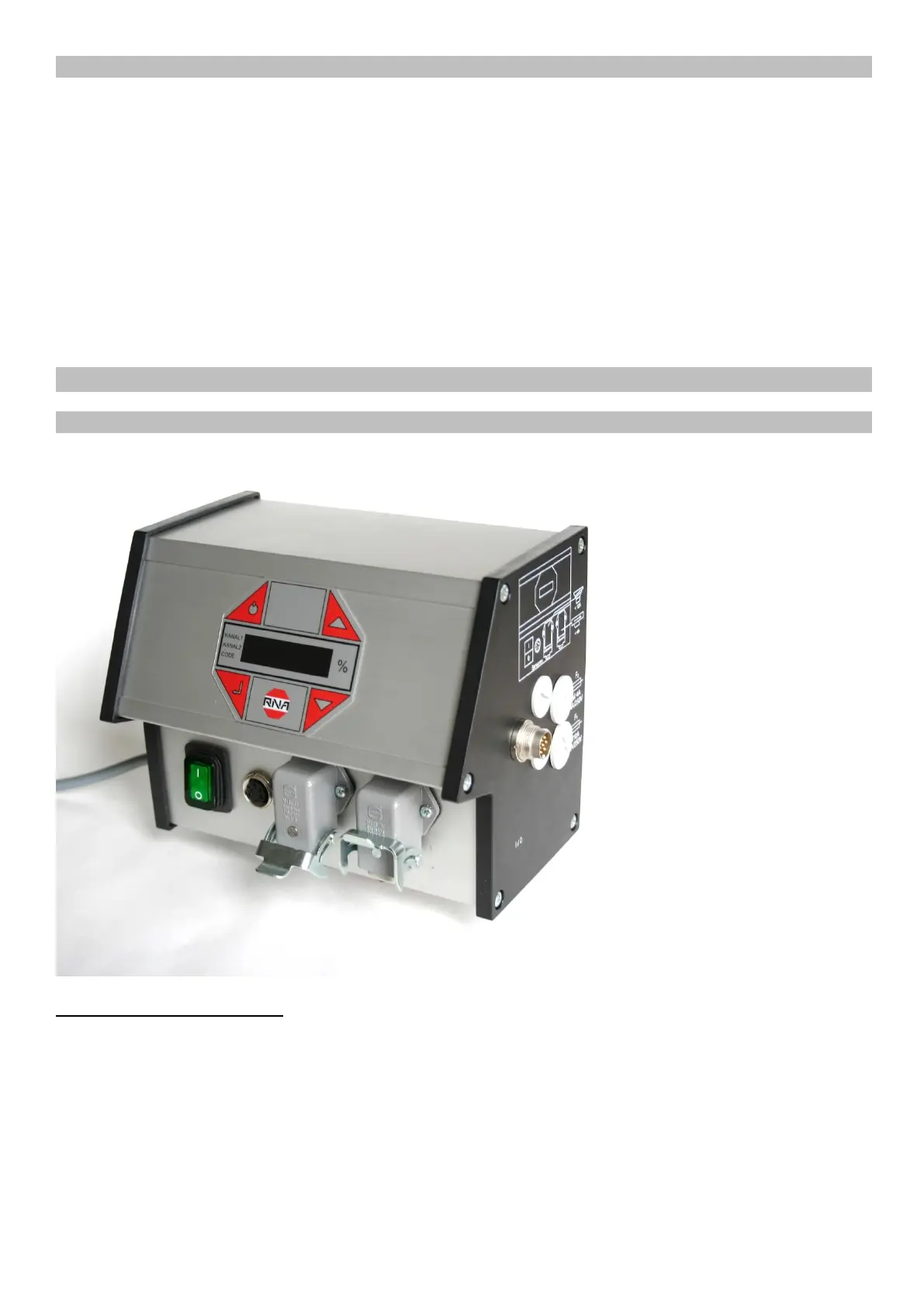
Connections and cable entry are located on the right side panel of the controller. The terminal block is located
behind the controller side panel.
Controller plug connections



 To Next Page