Do you have a question about the RNA ESK 2000 and is the answer not in the manual?
Provides guidance on product selection, installation, operation, extensions, and accessories.
Explains the meaning of notices and hazard symbols used in the document.
Outlines fundamental safety measures to prevent severe injury and damage.
Specifies that only qualified electricians or instructed persons should work on electrical equipment.
Details directives for intended use, commercial applications, and EMC considerations.
Highlights that residual hazards may persist and require user risk assessment.
Advises paying attention to warning signs fitted to the device for safety.
Warns that incorrect parameter settings can cause drive magnet overheating.
Covers protection against accidental contact and requirement for closed slots.
Details features like feed rate output, sensor inputs, relay outputs, and keypad.
Lists directives and harmonised standards the controller complies with.
Provides detailed technical specifications like voltage, current, delays, and operating temperature.
Lists available accessories with their designations and part numbers.
Lists essential checks before connecting power and switching on the controller.
Advises setting controller to minimum output before commissioning or after repairs.
Explains the two modes of operation (asymmetric half-wave and symmetric full-wave).
Describes how the operating mode is determined by a wire jumper in the drive connector.
Explains the function of sensor inputs and their basic assignments.
Details how to connect NPN or PNP sensors, including diagrams for different types.
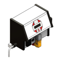
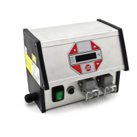
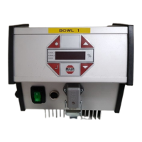
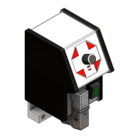
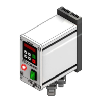
Provides an overview of the controller's front panel, including buttons and connectors.
Lists the functions of the main disconnect switch and connectors XS3, XS1, XS4.
Explains the functions of the display buttons and indicators.
Details the procedure for starting up the controller and possible display indications.
Describes how to navigate the main menu, enter setpoints, and change parameters.
Introduces various codes for programming controller functions like settings, sensors, and saving.
Sets vibration amplitude, enabling, soft start/stop delays, and drive selection.
Activates and configures sensor inputs 1 and 2, including signal inversion and delays.
Links activated sensor inputs for various logic functions like AND, OR, Min/Max.
Monitors sensor status and triggers alarms or stops based on time or conditions.
Allows setting the feed rate using an external 0-10V voltage input.
Covers saving, inhibiting, and retrieving controller parameters and settings, including factory defaults.
Indicates the supply voltage was too high and requires checking.
Signals a response issue with the cycle watchdog or product flow malfunction.
Indicates a problem with the controller's memory requiring repair.
| Brand | RNA |
|---|---|
| Model | ESK 2000 |
| Category | Controller |
| Language | English |