Rhein-Nadel Automation GmbH 8
VT-BA-ESK2000_EN_2023.docx
Vibratory drive systems by RNA do not require the operator to take care of selecting the right operating mode.
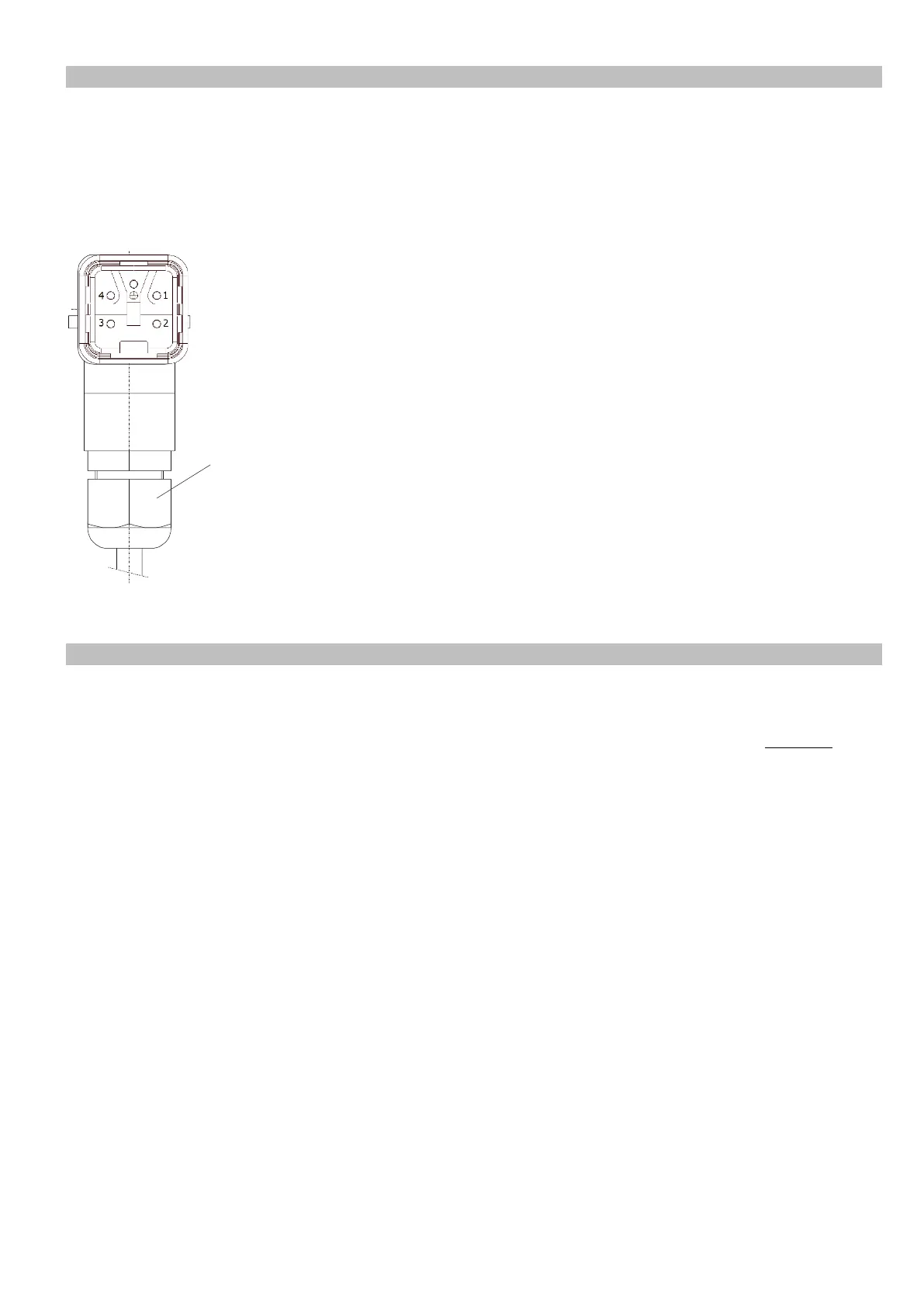
The operating mode is determined by a code in the RNA vibrating drive connector. A wire jumper from pin 3
to 4 in the connector switches the controller to mode 2: 100 or 120 Hz. In the absence of this wire jumper the
controller operates in mode 1: 50 or 60 Hz.
The RNA vibratory drive systems come with the right code in the connector.
Mode changes are made only and exclusively via the coding in the vibrating drive connector.
(Where frequency controllers with selectable output frequency are used, an EMC metal gland and a shielded
cable are provided.)
Two sensor inputs are integrated into the controller. They enable you to implement accumulation checks,
level checks, cycle monitoring and other monitoring tasks. The following basic assignments are made: Sen-
sor input 1 acts on channel 1, unless otherwise programmed in menu C006. Sensor input 2 is provided for
additional functions, see sensor linkage. The sensor inputs can be evaluated only if they are activated in
codes C004, C005. For sensor connection (connector XS3) please refer to the connection diagram.
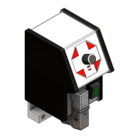
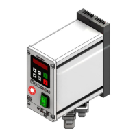
M20 gland
Black: 50/60Hz vibrating frequency
Grey: 100/120Hz vibrating frequency
(EMC metal gland if frequency controllers are
used.)