EasyManua.ls Logo

Roadmaster Blackhawk 2 All Terrain - User Manual

Roadmaster Blackhawk 2 All Terrain
4 pages
Print Icon
To Next Page IconTo Next Page
Loading...
Tow bar rated
at 10,000 pounds
ROADMASTER, Inc. 6110 N.E. 127th Ave. Vancouver, WA 98682 800-669-9690 Fax 360-735-9300 www.roadmasterinc.com
Owners and installers
must read the
installation instructions
and carefully note
the warnings!
Quick-disconnect parts list:
(2) quick-disconnects
(parts “A” and “B”)
(2) safety plates (“C”)
All mounting hardware
Figure 1
T
his tow bar is equipped with a quick-disconnect” (or, QD”) system.
Before connecting the tow bar to the vehicle, first install the compo-
nents of the QD system to the mounting brackets.
Note: the quick-disconnect system is not used with ROADMASTER
‘MS’ or ‘MX’ series mounting brackets. If the towed vehicle has MS or
MX brackets, proceed to “Connecting the tow bar.” The quick-disconnect
system should be reserved, however, for subsequent vehicles which may
not have these brackets.
1. First, attach the quick-disconnects (“QDs,” parts “A” and “B” in Figure
1) to the tow bar mounting brackets. Attach the QDs so that the vertical
pin on each is pointing up, as shown in Figure 1.
Attach part A” on the passenger side, and part “Bon the driver side.
Use the supplied ½" x 1¾" bolts, the two safety plates (parts “C”), and the
flat washers, lock washers and nuts, as shown in Figure 1.
Note: both QDs have an extra hole “D” in Figure 1 for safety cable
attachment. Mount parts “A” and “B” so that the “D” holes are to the out-
side.
Do not tighten any of the bolts leave them loose for now they will
be tightened later.
Use all mounting hardware and both safety plates. If all supplied
materials are not used, the quick-disconnects, the quick-disconnect
bases or other components may vibrate loose, which may cause prop-
erty damage, personal injury or even death.
2. Now, test-fit the crossbar — lower the crossbar (Figure 2) over the quick-
disconnects. The vertical pins at the top of both QDs should fit through
the top holes at the ends of the crossbar (Figure 2), and the vertical pins
at the bottom of the crossbar should fit through the lower holes on the
quick-disconnects (Figure 2).
3. Both quick-disconnects must be positioned so that the crossbar is cen-
tered to the front of the vehicle measure the distance between the side
of one QD and the side of the mounting bracket it is attached to. Then,
make certain there is an equal distance between the other QD and the
other mounting bracket.
The quick-disconnects must be centered on the mounting brackets.
If they are attached too far to the left or the right, the tow bar will
not be centered on the towed vehicle, which will cause excessive tire
wear and other consequential, non-warranty damage.
4. Once the crossbar slides on and off easily, torque the four bolts to 75
ft./lbs.
Again, test-fit the crossbar over the QDs, to verify that the crossbar
slides on and off easily. If it does not, adjust the QDs again.
5. Both linch pins must be inserted through the upper holes in the vertical
pins in parts “A” and “B,” as shown in Figure 2.
Both linch pins must be locked. The rings are spring-loaded — they must
be snapped over the pins, with the curved side of the linch pin touching
the ring, in order to keep the QD bases secure.
Towing vibrations will force the linch pins out unless they are proper-
ly locked in place over the vertical pins on both quick-disconnects.
Failure to properly install the linch pins will result in tow bar mal-
function, loss and damage to the vehicle and property, personal injury
or even death.
Figure 2
1
Installing the ‘quick-disconnect’ system
Installation Instructions
All specifications subject to change without notice
853329-04 12/11
Question and Answer IconNeed help?

Do you have a question about the Roadmaster Blackhawk 2 All Terrain and is the answer not in the manual?

Summary

Installing the Quick-Disconnect System

Attaching Quick-Disconnects

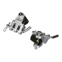
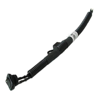
Attach quick-disconnects (QDs) to tow bar mounting brackets, ensuring correct pin orientation and hardware usage.

Test-fitting the Crossbar

Lower the crossbar over the quick-disconnects to verify proper pin alignment with the top and bottom holes.

Centering Quick-Disconnects

Ensure quick-disconnects are centered on mounting brackets for correct tow bar alignment and to prevent tire wear.

Securing and Re-testing Crossbar Fit

Torque mounting bolts to 75 ft./lbs. and re-test crossbar fit for easy sliding and removal.

Inserting and Locking Linch Pins

Insert linch pins through upper holes in vertical pins and lock them securely to prevent detachment.

Installers Safety Checklist

Towing Level and Operation

Advise owner on tow bar leveling ('Safe Zone') and demonstrate proper operation and connection/disconnection.

Safety Cable Requirements

Instruct owner on using safety cables, selecting them based on towed vehicle weight, and ensuring proper connection.

Vehicle Preparation for Towing

Ensure vehicle is suitable for towing, equipped with necessary transmission/driveline disconnects, and follow manufacturer prep procedures.

Welding Precautions

Do not use tow bar as a ground for welding; avoid welding to the vehicle or altering mounting holes to preserve warranty.

Stay Within the Safe Zone

Defining the Safe Zone

Tow bar must be within three inches above or below level to prevent undue strain and system failure.

Measuring for Safe Zone Compliance

Measure distance from motorhome receiver to ground and from base pin to ground; difference must be within three inches.

Adjusting for Safe Zone

Use hitch accessories (Hi-Low Hitches, Drops) to adjust receiver height if not within the Safe Zone; non-compliance voids warranty.

Connecting and Disconnecting the Tow Bar

Connecting Procedure

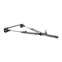
Attach QD system, drive vehicle close, secure with hitch pin, rotate arms up, then down to horizontal for connection.

Disconnecting Procedure

Reverse connection steps: rotate arms up, pull linch pins, detach from motorhome, and secure QD system.

Handling Safety

Use caution to avoid pinching hands or fingers between moving components during connection/disconnection.

Proper Installation of Safety Cables

Safety Cable Attachment

Connect snap hooks to hitch receiver or frame loops; use quick links for attachment and removal of safety cables.

Crossing Safety Cables

Cross safety cables under the hitch receiver to prevent tow bar dragging and 'pole vaulting' if separation occurs.

Using Multiple Safety Cables

Use both long and short safety cables as required by law and for system integrity; secure connections with tightened quick links.

Overview

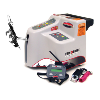
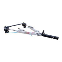
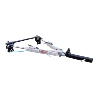
The BlackHawk 2 All Terrain tow bar is a robust towing system designed for connecting a towed vehicle to a motorhome. It is rated for a maximum carrying capacity of 10,000 pounds, making it suitable for a wide range of vehicles. The system incorporates a "quick-disconnect" (QD) feature for easy attachment and detachment of the tow bar components to the mounting brackets on the towed vehicle.

Function Description:

The primary function of the BlackHawk 2 is to provide a secure and stable connection between a towing vehicle (motorhome) and a towed vehicle. It ensures that the towed vehicle tracks properly behind the motorhome. The quick-disconnect system allows for the tow bar arms to be easily attached and removed from the vehicle's mounting brackets, enhancing convenience for users who frequently connect and disconnect their towed vehicles. The tow bar is designed to be used with specific mounting brackets that are bolted to the towed vehicle's frame or unibody.

Important Technical Specifications:

  • Tow Bar Rating: 10,000 pounds maximum carrying capacity.
  • Quick-Disconnect System: Includes two quick-disconnects (parts "A" and "B"), two safety plates ("C"), and all necessary mounting hardware. These components attach to the tow bar mounting brackets.
  • Mounting Hardware: Utilizes 1½" x 13½" bolts for attaching the quick-disconnects to the mounting brackets.
  • Linch Pins: Essential for securing the quick-disconnects to the vertical pins. They are spring-loaded and must be properly locked to prevent detachment during towing.
  • Safety Cables: The system emphasizes the use of safety cables, which must meet or exceed the towed vehicle's weight. For vehicles weighing 6,000 pounds or less, 6,000-pound rated cables are required. For weights between 6,000 and 8,000 pounds, 8,000-pound capacity cables (part numbers 648 or 649) are needed. For vehicles between 8,000 and 10,000 pounds, 10,000-pound capacity safety cables or chains are mandatory.
  • "Safe Zone" for Tow Bar Levelness: The tow bar must be within three inches above or three inches below the level of the motorhome hitch receiver. Deviations outside this "Safe Zone" can cause excessive wear and damage.
  • Crossbar: Connects the quick-disconnects, ensuring proper alignment and stability. It should slide on and off easily once the quick-disconnects are correctly positioned.
  • Torque Specifications: The four bolts connecting the quick-disconnects to the mounting brackets must be torqued to 75 ft./lbs.

Usage Features:

  • Quick-Disconnect Installation:
    1. Attach quick-disconnects (parts "A" and "B") to the tow bar mounting brackets, ensuring the vertical pin on each points upward. Part "A" goes on the passenger side, "B" on the driver side.
    2. Use the supplied bolts, safety plates ("C"), flat washers, lock washers, and nuts. The "D" holes for safety cable attachment must face outward.
    3. Initially, leave bolts loose for adjustment.
    4. Test-fit the crossbar: it should slide easily over the vertical pins of the quick-disconnects.
    5. Center the crossbar by ensuring equal distance between each quick-disconnect and its respective mounting bracket.
    6. Once centered and sliding easily, torque the four bolts to 75 ft./lbs.
    7. Insert and lock linch pins through the upper holes in the vertical pins to secure the QD bases. The spring-loaded rings must snap over the pins.
  • Connecting the Tow Bar:
    1. Ensure quick-disconnects are properly installed on the mounting brackets.
    2. Position the towed vehicle within three to three-and-a-half feet of the motorhome hitch receiver.
    3. Insert the tow bar stinger into the motorhome hitch receiver and secure it with a hitch pin and clip.
    4. Rotate both tow bar arms upward to a vertical position.
    5. Push the release latch forward to bring both arms down to a horizontal position.
    6. Swing both arms away from you and align them with the quick-disconnect bases on the towed vehicle.
    7. Push the tow bar arms onto the quick-disconnect bases until the locking mechanisms engage.
    8. Insert the linch pins through the holes in the quick-disconnect bases and the vertical pins of the tow bar arms, securing them.
    9. Attach safety cables: cross them under the hitch receiver and connect them from the driver's side of the tow bar to the passenger side of the motorhome, and vice versa. Use quick links for easy attachment.
    10. Connect electrical wiring and break-away cable.
  • Disconnecting the Tow Bar:
    1. Ensure the towed vehicle is on level ground, with the motorhome in park and emergency brake set.
    2. Disconnect electrical wiring, safety cables, and any other towing accessories.
    3. Remove the linch pins from the quick-disconnect bases.
    4. Pull the release handles on each tow bar arm to release the locking mechanisms.
    5. Remove the tow bar arms from the quick-disconnect bases.
    6. Remove the stinger from the motorhome hitch receiver.

Maintenance Features:

  • Regular Inspection: Periodically check all components for signs of wear, damage, or looseness. This includes the quick-disconnects, mounting hardware, linch pins, safety plates, and safety cables.
  • Safety Cable Care: Safety cables must be carefully routed to prevent pinching, fraying, scraping, or damage. They should not drag on the ground. Replace cables immediately if any signs of wear or damage are observed.
  • Linch Pin Security: Always ensure linch pins are properly locked in place over the vertical pins. Failure to do so can lead to tow bar malfunction and detachment.
  • "Safe Zone" Adherence: Regularly verify that the tow bar remains within the "Safe Zone" (no more than three inches above or below level). If not, use hitch accessories (Hi-Low Hitches, Hi-Low Drops, Dual Hitch Receivers) to adjust the hitch receiver height. Towing outside the "Safe Zone" will void the ROADMASTER warranty.
  • No Welding or Altering: The tow bar should never be welded to the vehicle, nor should any pre-punched mounting holes be altered. Welding or altering voids the warranty.
  • Proper Alignment: Ensure the quick-disconnects are centered on the mounting brackets to prevent excessive tire wear and non-warranty damage to the towed vehicle.
  • Cleanliness: Keep the cable guides clean to prevent damage to safety cables and electrical cords.

Warnings and Cautions:

  • Hardware Usage: Use all supplied mounting hardware and both safety plates. Incomplete installation can lead to components vibrating loose, causing property damage, personal injury, or death.
  • Linch Pin Locking: Towing vibrations will force linch pins out unless properly locked. Failure to do so can result in tow bar malfunction, loss, damage, personal injury, or death.
  • Tow Bar Levelness: Towing outside the "Safe Zone" causes significant wear and tear, potentially leading to system failure.
  • Safety Cable Capacity: Safety cables must meet or exceed the towed vehicle's weight. Undersized cables will fail.
  • Safety Cable Routing: Improperly routed safety cables can become damaged or detach.
  • Quick Links: Ensure quick links are fully tightened with the loop closed to prevent safety cables from detaching.
  • Tow Bar Arms: Never release the tow bar arms when they are in the vertical position, as they can fall and cause severe personal injury.
  • Tow Bar Attachment: Attach the tow bar with locking mechanisms and release latch pointing up to avoid damage.
  • Crossed Safety Cables: Always cross safety cables under the hitch receiver to prevent the tow bar from dragging or "pole vaulting" if it separates from the motorhome.
  • Handling: Use caution when handling the tow bar to avoid pinching, cutting, or injuring hands or other body parts between moving components.
  • Vehicle Suitability: Ensure the towed vehicle is suitable for towing and equipped with necessary components (e.g., transmission lube pump, axle disconnect) to prevent severe damage.
  • No Welding Ground: Do not use the tow bar as a ground for welding, as it can damage the locking mechanism.

Roadmaster Blackhawk 2 All Terrain Specifications

General IconGeneral
BrandRoadmaster
ModelBlackhawk 2 All Terrain
CategoryAutomobile Accessories
LanguageEnglish

Related product manuals