Do you have a question about the Roadmaster BrakeMaster 9100 Series and is the answer not in the manual?
Explains safety symbols, critical warnings, and essential pre-installation checks.
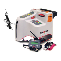
Attaches the rear quick coupler and routes the monitor wire to the motorhome dashboard.
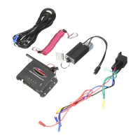
Mounts the LED indicator on the dashboard and connects its power and ground wires.
Identifies connection points at air brake relay valve, air booster housing, or use of tees.
Ensures the motorhome is safely supported and blocked before releasing the parking brake.
Connects air line to an open port on the air brake relay valve using fittings and sealant.
Connects air line to the main brake air booster housing, verifying the port.
Connects air line using a tee to the service port if no open port is available.
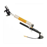
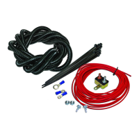
Assembles the air line with compression nut, ferrule, and brass insert for a secure connection.
Routes the air line, avoiding heat, sharp edges, and kinks for safety and functionality.
Connects the air line to the female quick coupler at the rear of the motorhome.
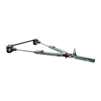
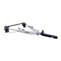
Connects tow bar, prepares towed vehicle, and secures air lines and monitor wiring.
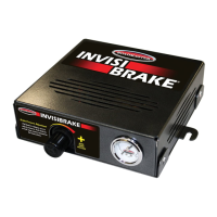
Checks the air system for leaks using a leak check solution with an assistant.
Verifies air cylinder extension/retraction with motorhome brake pedal operation.
Confirms the monitor LED illuminates correctly when the brake pedal is depressed.
Tests the breakaway system by removing the pin, confirming cylinder extension and retraction.
Verifies towed vehicle brake lights and turn signals operate correctly with motorhome signals.
Diagnoses why the monitor LED fails to illuminate, checking connections and wiring.
Troubleshoots lack of system response, checking engine, brake release, and air line connections.
Addresses issues where the air cylinder does not retract, checking for kinks or debris.
Resolves abrupt braking and 'flat-spotting' by managing towed vehicle vacuum and brake pressure.
| Brand | Roadmaster |
|---|---|
| Model | BrakeMaster 9100 Series |
| Category | Automobile Accessories |
| Language | English |