Do you have a question about the Roadmaster BrakeMaster 9000 and is the answer not in the manual?
Indicates a potentially hazardous situation leading to property damage or injury/death.
Indicates a potentially hazardous situation leading to property damage or minor/moderate injury.
Check ROADMASTER website for specific installation details for your vehicle.
Using metric-to-standard T-fittings for brake line connections if applicable.
Need for steel brake line if motorhome has one-piece brake line or difficult unions.
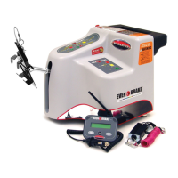
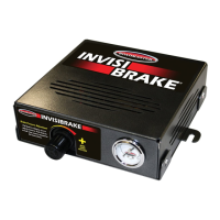
Choose a clean, dry area within 20 feet of the starting battery for mounting.
Mount compressor horizontally or vertically with drain valve pointing down.
Position compressor and drill pilot holes for mounting screws.
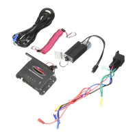
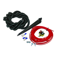
Route battery wires and ignition power wire to the compressor.
Install 20-amp fuse for red wire and 10-amp fuse for blue wire at battery.
Connect red, black, and blue wires to battery and ignition source.
Choose location near brake unions or fittings to tee into the brake line.
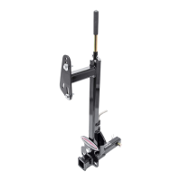
Mount proportioning valve bracket securely on the motorhome frame.
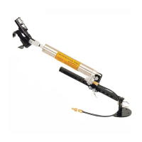
Deplete vacuum from the power brake booster before installing the valve.
Check and fill the master cylinder reservoir with brake fluid to the maximum mark.
Disconnect brake line from the union, catch fluid, and plug the line.
Drill holes and attach the proportioning valve bracket to the frame.
Connect a black wire from the solenoid valve to a good chassis ground.
Connect brake tees to factory lines and proportioning valve with supplied brake lines.
Avoid kinking the brake line; a kink can cause brake failure.
Loosen the bleeder valve to remove air from the proportioning valve.
Specific procedures for bleeding ABS systems with pressurized bleeders or accumulator.
Bleed air from only one wheel cylinder on the proportioning valve line.
Detailed steps for bleeding using the specific brake line method with an assistant.
Procedure for bleeding all brake lines when air enters the master cylinder.
Using vacuum systems to draw air out of the brake lines.
Using pressurized systems to push fluid and air out of the brake lines.
Identify brake light system type (separate or combined) for solenoid connection.
Connect solenoid valve wire to motorhome brake light wire based on system type.
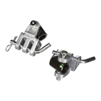
Mount female quick coupler at the rear of the motorhome.
Route air lines from compressor to proportioning valve and then to coupler.
Connect air lines using compression fittings, nuts, ferrules, and brass inserts.
Route wiring from rear of motorhome to dashboard for monitor system.
Mount and connect the LED indicator on the motorhome dashboard.
Connect the patch cord between motorhome and towed vehicle air lines and monitor wires.
Connect red and black wires from air compressor to motorhome starting battery.
Check that all components are connected and ready for towing.
Apply leak check solution to all air system joints and fittings to ensure they are airtight.
Depress and release motorhome brake pedal to check air cylinder extension/retraction.
Confirm the LED illuminates when the brake pedal is depressed and turns off when released.
Test towed vehicle brake lights and turn signals operation with motorhome controls.
Check connections, light braking, fuses, and Brake-Lite Relay for LED issues.
Verify motorhome engine running, air line connections, and solenoid valve wiring.
Check for air leaks, closed drain valves, and proper quick coupler function.
Ensure motorhome engine is running and check air lines for kinks or damage.
Address abrupt braking or tire issues due to vacuum or active systems.
Adjustments for active braking systems or vehicles without power brakes.
| Brand | Roadmaster |
|---|---|
| Model | BrakeMaster 9000 |
| Category | Automobile Accessories |
| Language | English |