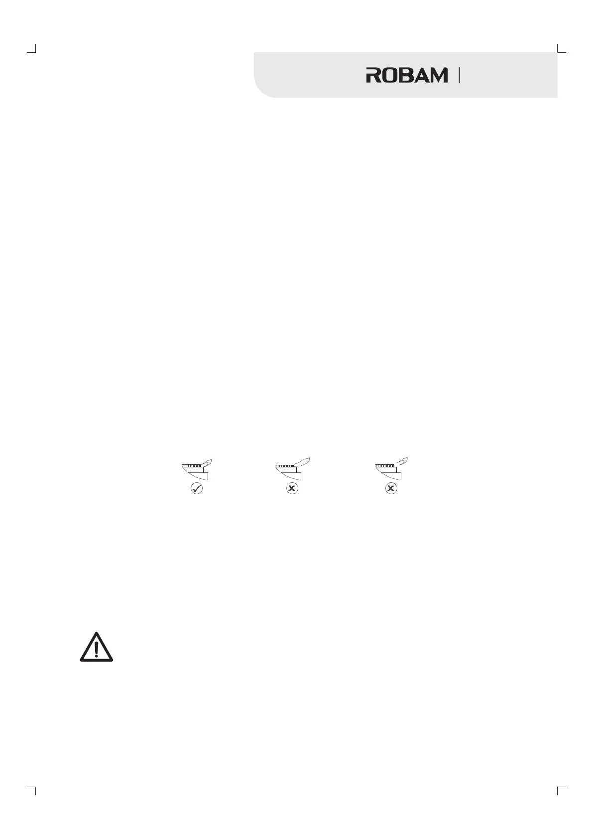
Normal
( Combustion well)
Yellow flame
(Air deficiency)
Left flame
(Air superabundance)
Note:
◆the cook top must be installed with provision to allow the gas to be turned off and disconnected for servicing
and removal of the appliance as required from gas supply.
◆The gas pressure must be set by an approved gas fitter and a full operational test and a test forpossible
leakages must be carried out by the gas fitter after installation.
◆The gas pressure must be set by the approved gas fitter as shown on the data plate natural gas 1kPa.
◆Minimum flow adjustment is no need, because minimum flow has been adjusted when manufacturing.If the
minimum flow is not working properly, please contact local dealer to solve the problem.contact information
see“After Sale Service”
My appliance isn't working correctly
DO NOT ATTEMPT TO REPAIR THE APPLIANCE YOURSELF.
◆
◆The appliance must be accessible for the engineer to perform any necessary repair. If your appliance is
installed in such a way that an engineer is concerned that damage will be caused to the appliance or your
kitchen, then he will not complete a repair.
Please note that if an engineer is asked to attend whilst the product is under guarantee and finds that the
problem is not the result of an appliance fault, then you may be liable for the cost of related costs.
8
Gas Hob
Note:
Gas hose assemblies or Limited flexibility hose shall be purchased by the user.
The gas connection point must be between 800 to 850mm above the floor and in theregion outside the width
of the appliance to a distance of 250mm.
Pressure Regulator model: RTZ-ED.
Dismantling tools: adjustable spanner.
Remove hose connector before installation.
Please connect the gas regulator with the pipe interface of the gas company.
◆Put the gas seal inside of the 15mmx1/2 conical thread connector.
◆Fully tighten the 15mmx1/2 conical thread connector and seal onto the gas rail.
◆IMPORTANT: The connector must be positioned the right way up, as shown in the picture above.
Pressure test point
- This is provided in the gas regulator.
- Remove the screw, connect the hose from the pressure gauge.
- Turn on the gas to the semi-rapid burner and manually light the burner.
- The pressure is shown on the data plate.
- To increase the pressure, loosen locking nut and turn clockwise.
- Disconnect gauge and replace test point screw.
WARNING: check the right positioning of the gas regulator. The arrow on the back of the gas regulator must
be oriented toward the connector.
IMPORTANT: On completion carry out a gas leakage test.
After installation don't rotate fixed screw nut connecting with inlet gas pipe arbitrary and must be tested
leakage.(Method: Paint tenuous and neuter cleaning solution on the connecting part, then open the valve. If
there is air bladder, please close the valve and tighten screw nut, test it again until there is nothing leakage).
Test the appliance
After installing the cooktop, ignite all burners to check that they are operating correctly
- The flame must not go out on the lowest setting, or when the control is turned quickly from the highest
to the lowest setting.
- On the highest setting, the flame must have a distinctive and visible core.
- If any problem occurs, refer to the common faults and solutions.
”
”
 Loading...