5-4-
6
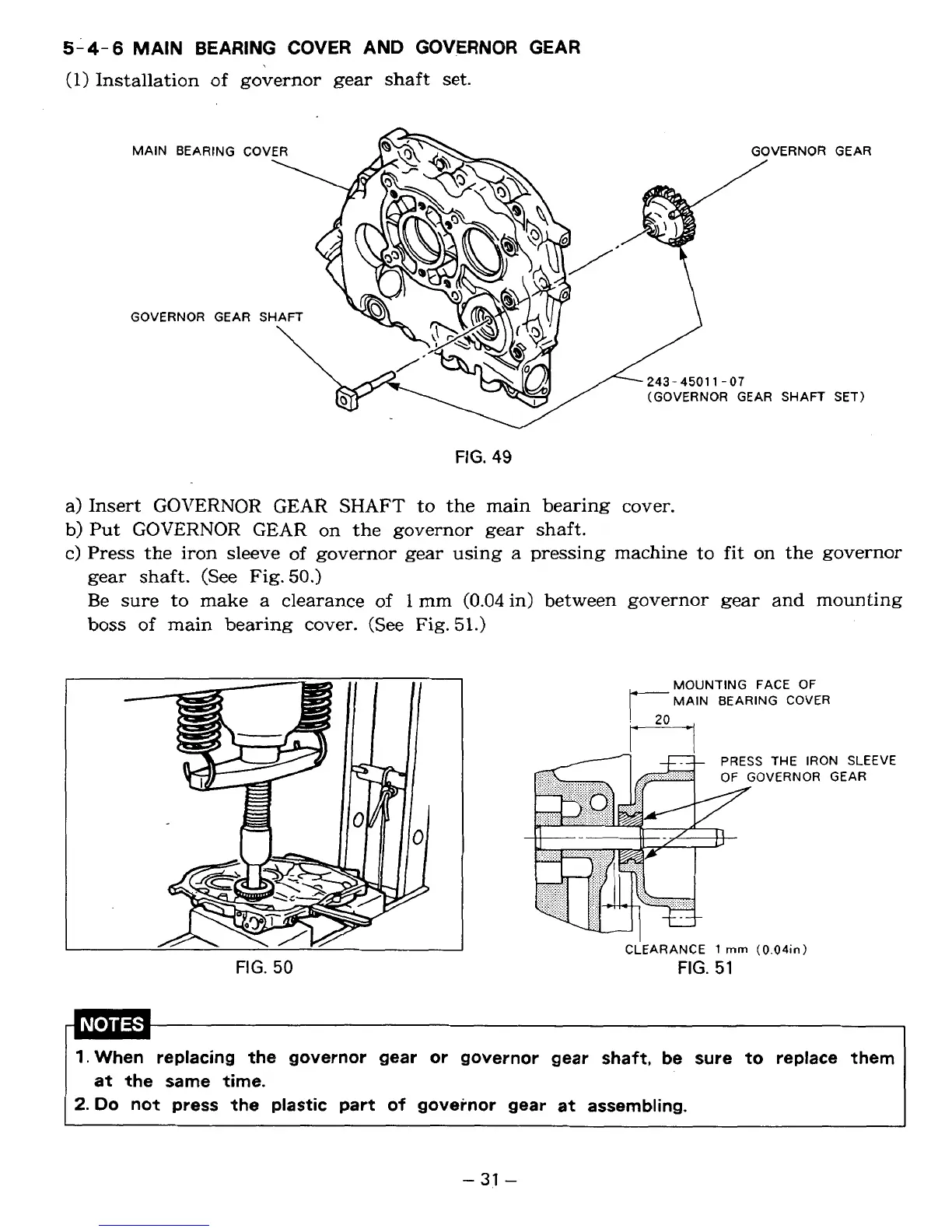
MAIN BEARING COVER AND GOVERNOR GEAR
(1)
Installation
of
governor gear
shaft
set.
MAIN BEARING COV VERNOR
GOVERNOR GEAR
S
243-4501 1-01
(GOVERNOR GEAR SHAFT
FIG.
49
GEAR
SET)
a) Insert
GOVERNOR
GEAR
SHAFT
to the main bearing cover.
b)
Put
GOVERNOR
GEAR
on
the governor gear shaft.
c) Press
the
iron sleeve
of
governor gear using
a
pressing machine
to
fit
on the governor
gear shaft. (See
Fig.
50.)
Be sure to make a clearance
of
1
mm
(0.04
in) between governor gear and mounting
boss
of
main
bearing cover. (See Fig.
5
1.)
FIG.
50
FACE
OF
MAIN BEARING COVER
S
THE IRON SLEEVE
OVERNOR GEAR
I
CLEARANCE
1
rnm
(0.04in)
FIG.
51
1.
When replacing the governor gear or governor gear shaft, be sure to replace them
2.
Do
not press the plastic part
of
governor gear at assembling.
at the same time.
-
31
-
 Loading...