-
9
-
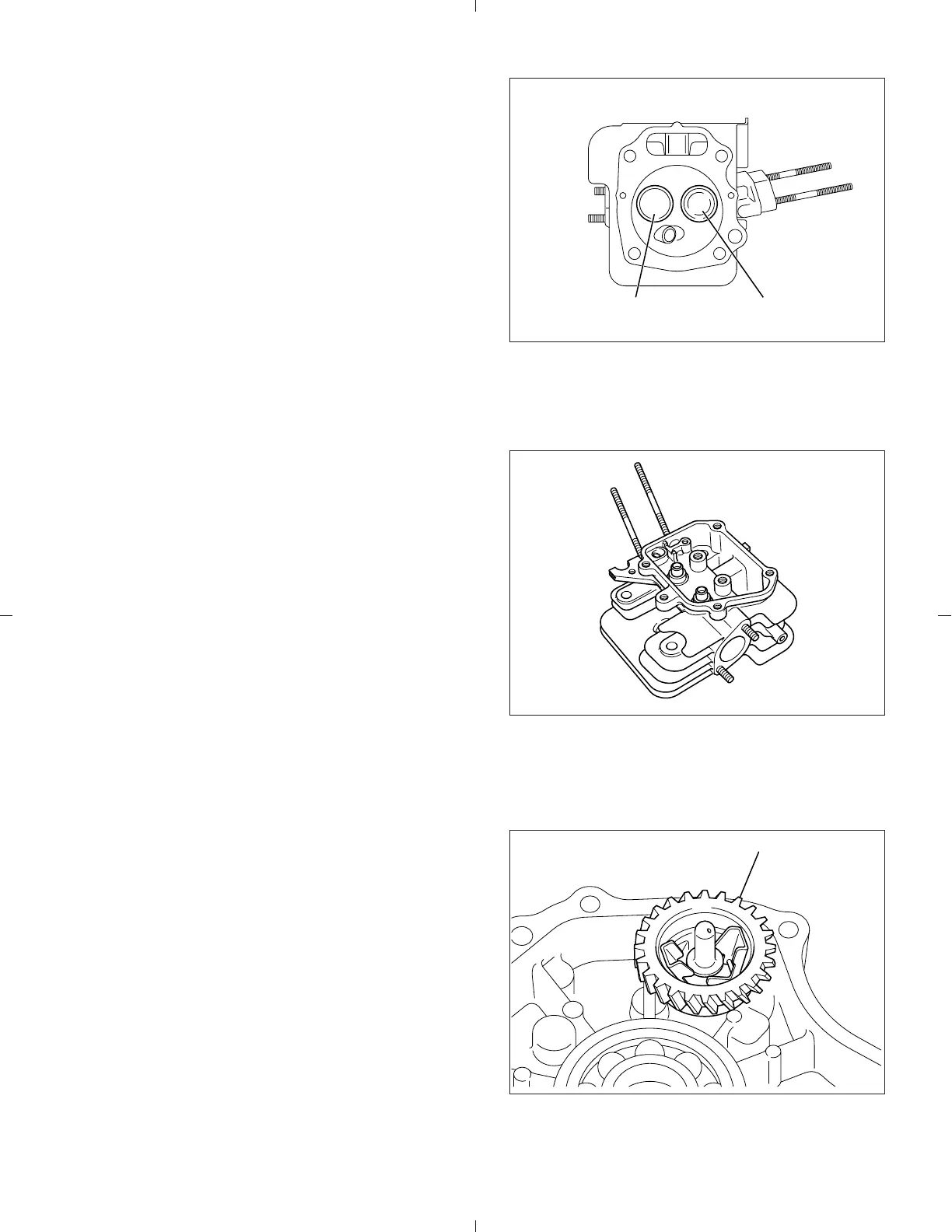
4-7 VALVE ARRANGEMENT
The intake valve is located on flywheel side of the
cylinder head.
Hard alloy valve seats are molded in the cylinder
head and stellite is fused to the exhaust valve face.
The cylinder baffle leads cooling air to the exhaust
valve area for the optimum cooling.
4-8 CYLINDER HEAD
The cylinder head is an aluminum die-casting
which utilizes semi-spherical type combustion
chamber for the high combustion efficiency.
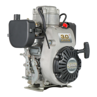
4-9 GOVERNOR SYSTEM
The governor is a centrifugal flyweight type which
ensures constant operation at the selected speed
against load variations.
The governor gear with governor weights is in-
stalled on the main bearing cover.
Fig. 4-7
Fig. 4-8
Fig. 4-9
EXHAUST VALVE INTAKE VALVE
GOVERNOR GEAR