-
38
-
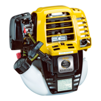
Valve clearance : 0.1 ± 0.03 mm
(0.0039
± 0.0012 in.)
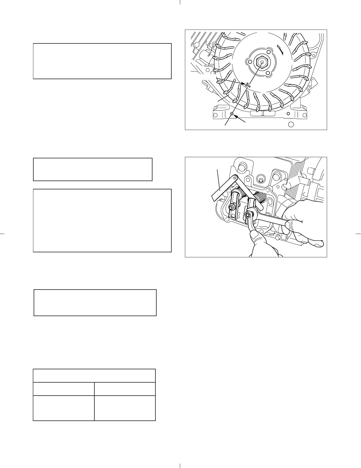
Note:
Temporally fit the flywheel in position for
easy operation.
THICKNESS
GAUGE
MARK "T"
THREAD HOLE
( a )
FLYWHEEL
5-4-10 VALVE CLEARANCE ADJUSTMENT
(1) Position piston at top dead center of compres-
sion stroke by matching the mark “T” of fly-
wheel with the thread hole (a) of crankcase.
(2) Loosen the nut on rocker arm and turn the pivot
to adjust the clearance between rocker arm
and valve stem end.
Tighten the nut on rocker arm.
(3) Install rocker cover and gasket.
Rocker cover M6 x 25 mm bolt : 4 pcs.
5-4-11 SPARK PLUG
Install spark plug to cylinder head.
Spark plug : NGK BP6ES
Fig. 5-37
Fig. 5-38
Note:
Check and adjust valve clearance while
engine is cold.
Check operation of valves by turning
crankshaft. Then recheck the valve clear-
ance.
Tightening torque
New spark plug Retightening
11.8 - 14.7 N・m
(120 - 150 kgf・cm)
(8.7 - 10.9 ft・lb.)
22.6 - 26.5 N・m
(230 - 270 kgf・cm)
(16.6 - 19.5 ft・lb.)
Tightening torque : 6.9 - 8.8 N・m
(70 - 90 kgf・cm)
(5.1 - 6.5 ft
・lb.)