-
40
-
5-4-15
BLOWER HOUSING AND RECOIL STARTER
(1) Attach blower housing to crankcase. Tighten
five flange bolts.
M6 x 12 mm flange bolt : 5 pcs.
Insert the high tension cord from the ignition
coil into the notch of the blower housing so
that not to pinch the cord.
(2) Install recoil starter to blower housing.
M6 x 8 mm flange bolt : 4 pcs.
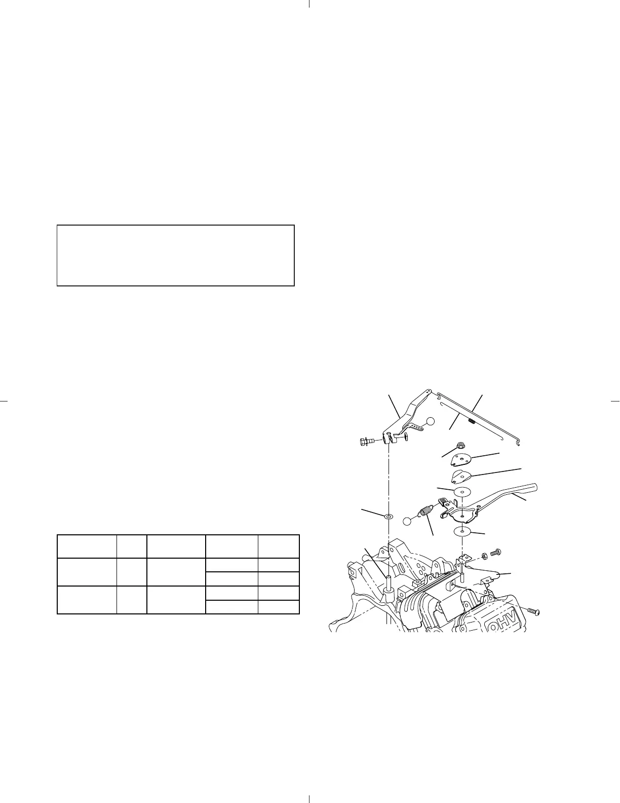
5-4-16 GOVERNOR, SPEED CONTROL
SYSTEM AND CARBURETOR
(1) Install governor lever to governor shaft.
Tighten locking bolt temporarily.
(2) Install speed control lever to cylinder baffle,
friction washer, self lock nut, etc. as shown in
illustration.
(3) Hook governor spring to proper holes of gov-
ernor lever and speed control lever.
(See Fig. 5-42 and below.)
Parts No. Color Application Frequency
Hooking
position
267-42501-03 Silver STD
60Hz 4 - C
50Hz 5 - C
267-42502-01 Gold Generator
60Hz 2 - C
50Hz 4 - C
(4) Install insulator and gaskets for carburetor to
cylinder head.
Note:
Be careful of pulling direction of starter
rope.
Fig. 5-41
A
A
GOVERNOR LEVER
WASHER
FRICTION
WASHER
FRICTION
WASHER
SELF
LOCK NUT
SPRING
WASHER
GOVERNOR
SPRING
GOVERNOR ROD
SPEED
CONTROL
LEVER
GOVERNOR
SHAFT
STOP PLATE
ROD SPRING
CYLINDER
BAFFLE 1
Discrimination of governor spring :