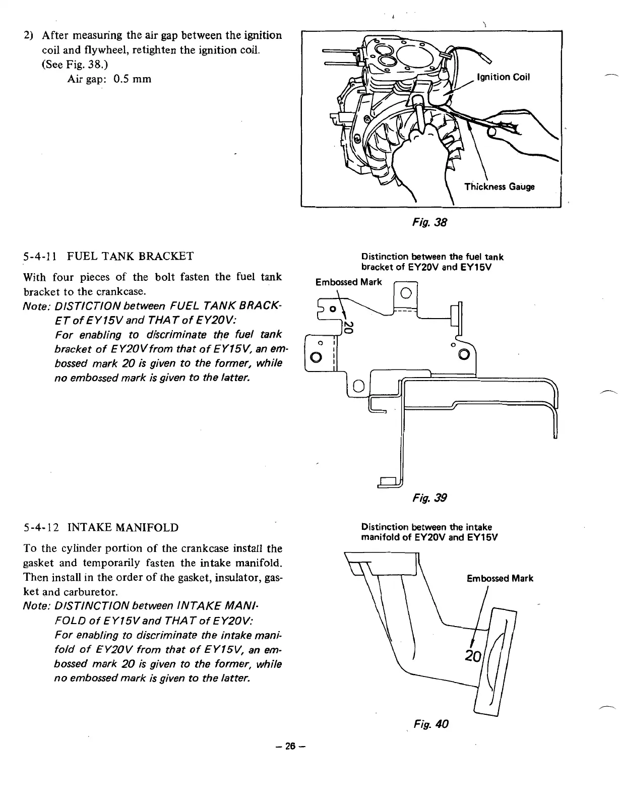
After measuring the air gap between the
ignition
coil and flywheel, retighten the ignition coil.
(See Fig.
38.)
Air gap:
0.5
mm
5-4-1
1
FUEL
TANK
BRACKET
With four pieces
of
the bolt fasten the fuel tank
bracket to the crankcase.
Note: DISTICTION between
FUEL
TANK
BRACK-
ETof EY15Vand THATof EY2OV:
For enabling to discriminate the fuel tank
bracket of EY20Vfrom that of
EYISV,
an em-
bossed mark
20
is
given to the former, while
no embossed mark
is
given to the latter.
5
-4-
12 INTAKE MANIFOLD
To
the cylinder portion
of
the crankcase install
the
gasket and temporarily fasten the intake manifold.
Then install
in
the order
of
the gasket, insulator, gas-
ket and carburetor.
Note: DISTINCTION between INTAKE MANI-
FOLD
of EYISVand THAT of EY20V:
for enabling to discriminate the intake mani-
fold of EY20V from that
of
EYISV, an em-
bossed mark
20
is
given to the former, while
no embossed mark
is
given to the latter.
L
I
Fig.
38
Distinction between the fuel tank
bracket
of
EY20V and EYl5V
Embossed Mark
-
\
0
1
01
I
0;
L
fig.
39
Distinction between the intake
manifold of EYZOV and EY
15V
U
Fig.
40
-
26
-