32
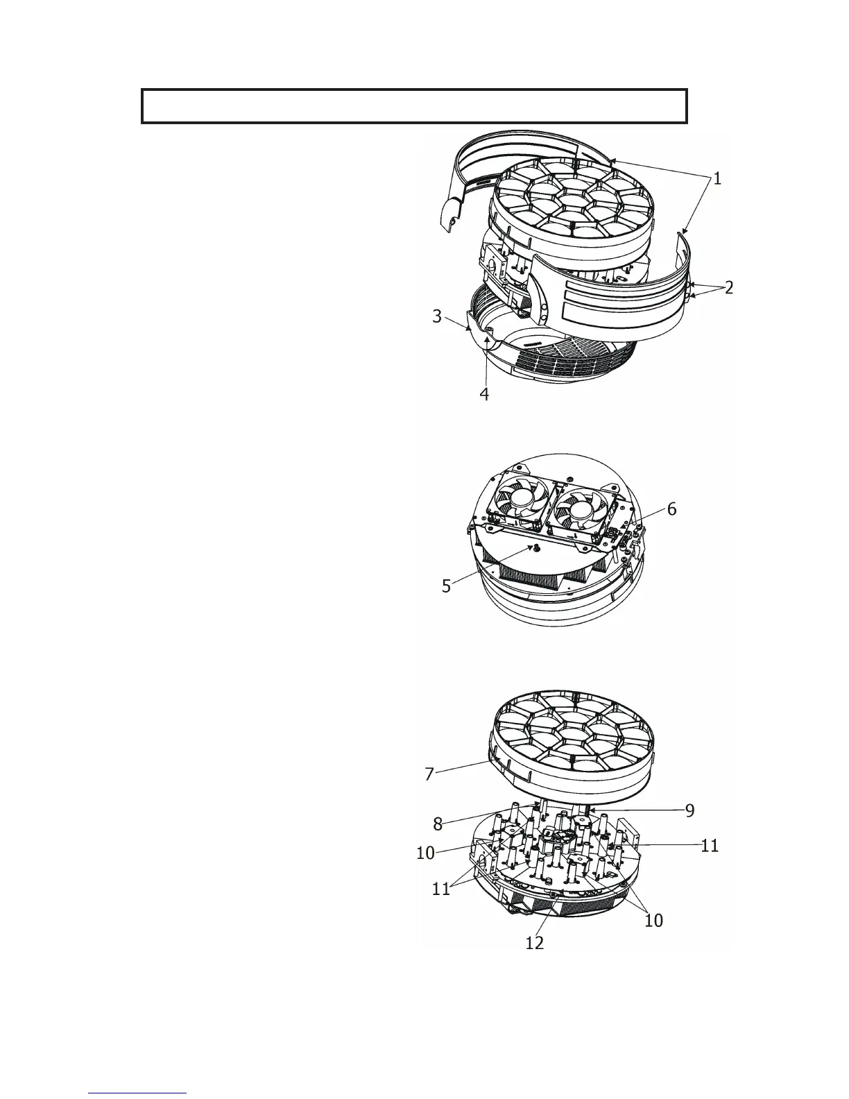
11.1 Removing the optical module
The following instructions are intended for service purposes only
.
To remove the optical module
1. Disconnect the xture from mains.
2. Loosen the four fastening screws (2) on each side
of the head covers (1) to remove the covers.
3. Loosen the four fastening screws (4) on back cover
of the head (3)
4. Unscrew the securing screw (5) from the
guide-pin. Its position is shown on the picture (the fan
connecting PCB (6) has to be on the right from the
securing screw (5)).
If you do not have access to the securing screw, push
the optical module (7) towards the fans. Do not touch
the plastic lenses bare hands.
DO NOT FORGET TO UNSCREW THIS SECURING
SCREW (5)!
5. Carefully take the optical module (7) out of the
guide-tubes (11) and motors (10).
To insert the optical module back
1. Connect the xture to mains and after xture reset
go to tab Manual Control, select item Zoom and set
it at 255 DMX.
2. Put the optical module (7) on the LED module
(12) in such a way that three guide-pins (8) aim into
guide-tubes (11) and three lead screws (9) aim into
motors (10).
3. Hold the optical module in this position and slowly
change the item Zoom from 255 DMX to 0 DMX.
Motors "draw" the optical module to the LED module
(12).
DO NOT TRY TO INSERT THE OPTICAL
MODULE BY A FORCE.
4. Run the Zoom Reset from tab Manual Control
or disconnect/connect the xture to mains.
5. Disconnect the xture from mains.
6. Screw the securing screw (5) back to the guide-pin.
DO NOT FORGET TO SCREW THIS SECURING
SCREW (5)!
7. Screw covers on the xture head.