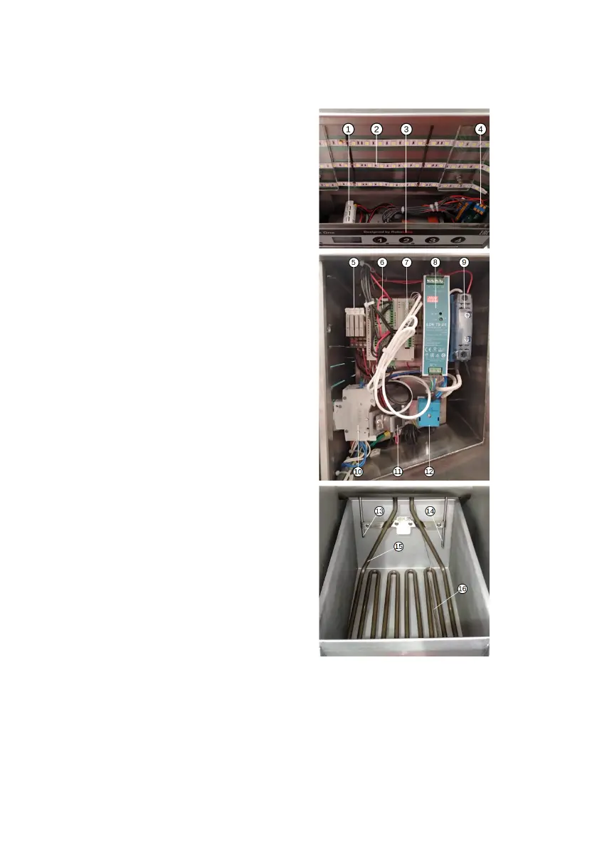
8.3 Electric components layout
1 – 4-digit display (DC3)
2 – LED stripes (HL1–HL4)
3 – Keypad (KE)
4 – Keypad socket (XS)
5 – Electromechanical relays (K1–
K4)
6 – Programmable logic controller
(DC1)
7 – Temperature regulator (DC2)
8 – Power supply unit (PSU)
9 – Solid-state relay (VS)
10 – Circuit breaker (QF)
11 – Buzzer (BZ)
12 – Thermal cut-out (AT)
13 – Temperature sensor (BT2)
14 – Temperature sensor (BT1)
15 – Heating element (EK)
16 – Thermal cut-out bulb (AT)
20