4
7. CAN Terminal Resistance Switch
Switch to ON or NC to connect or disconnect the 120 Ω terminal resistance, according to
CAN bus wiring regulations and other relevant regulations.
8. CAN cable
Receives the CAN controlling signal of the control panel. The bitrate of the CAN bus is 1
Mbps.
9. Serial Port
Connects to a USB-to-serial converter by soldering. Connect the USB-to-serial converter to
a computer to congure the parameters or update the rmware of the speed controller via
RoboMaster Assistant.
When the CAN bus command control is in use, the information of the position and
rotational speed of the rotor can be acquired. Make sure to consider the bandwidth of
the CAN bus wire when it is in use.
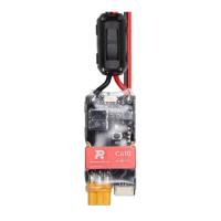
Serial Port
Side view:
RXD, TXD, and GND
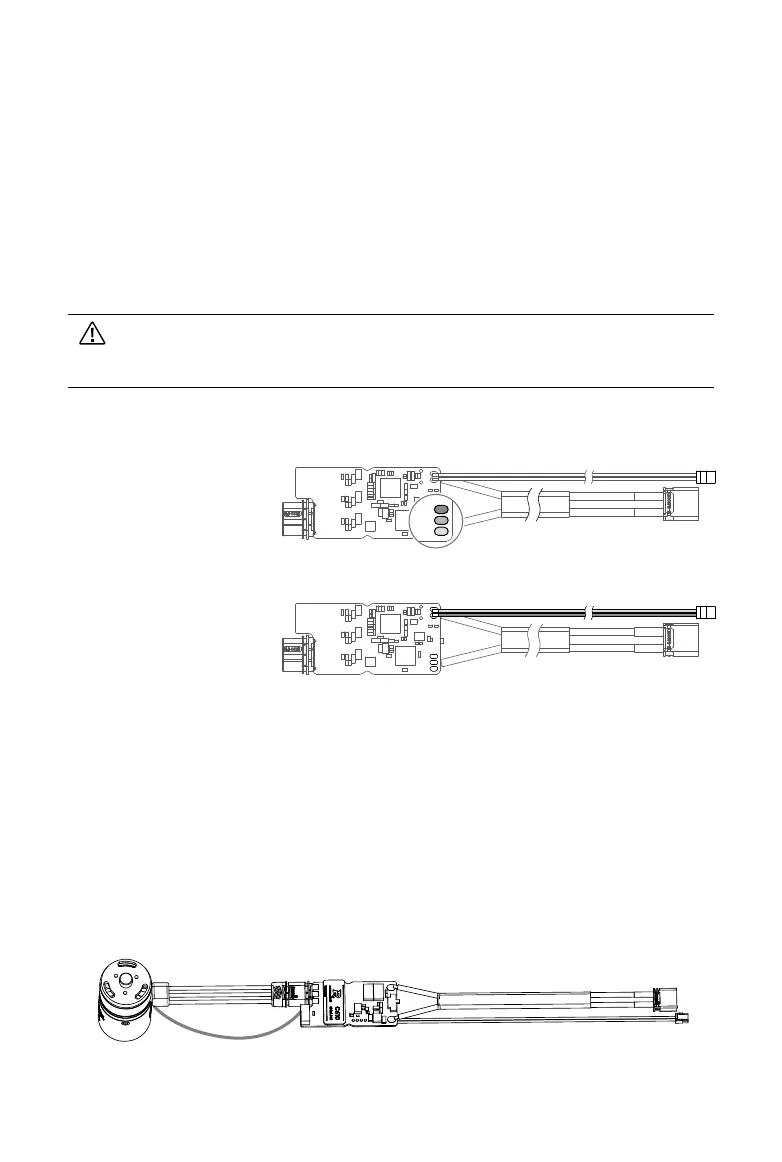
Connecting the Speed Controller
1. Connect the 4-pin cable of the motor to the 4-pin port on the speed controller.
2. Connect the 3-phase cable of the motor to the 3-phase port on the speed controller. Make
sure the cables are correctly connected.
3. Connect the CAN cable to the CAN port on the control panel.
4. Connect the power cable to a power supply.
CAN Cable
3-phase Cable
Power Cable
CAN Cable
Side view:
Red (CAN_H) and black
(CAN_L)
GND
TXD
RXD