The RoboMaster C610 Brushless DC Motor Speed Controller is a sophisticated electronic component designed for precise motor control within robotic systems, particularly those utilizing the RoboMaster platform. This user guide provides comprehensive information for its proper installation, configuration, and operation, emphasizing safety and optimal performance.
Function Description
At its core, the C610 is a brushless DC motor speed controller that leverages a 32-bit motor driver chip and Field-Oriented Control (FOC) technology. This advanced control method allows for highly accurate manipulation of motor torque, which is crucial for applications requiring precise movement and power delivery. The controller is specifically designed to be compatible with the M2006 P36 Brushless DC Gear Motor, forming a complete and integrated propulsion system.
The device acts as an intermediary between a control panel (or main controller) and the motor, receiving commands and translating them into precise motor actions. It provides power to the motor and, in turn, acquires critical feedback information such as the rotor's position and rotational speed. This data is then transmitted back to the control panel, enabling closed-loop control and real-time monitoring of the motor's status.
Key functional components include:
- Power Cable: Connects to a 24V power supply, providing the necessary operating voltage for the speed controller and the connected motor.
- 3-Phase Power Cable: Connects directly to the 3-phase power input of the M2006 motor, ensuring secure and efficient power transfer.
- 4-Pin Port: This dedicated port connects to the 4-pin cable of the M2006 motor. Its primary function is to acquire detailed position information of the rotor, which is essential for FOC and precise control.
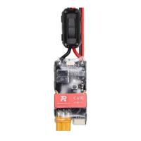
- CAN Cable: This port is used for receiving CAN (Controller Area Network) controlling signals from the control panel. The CAN bus operates at a bitrate of 1 Mbps, facilitating high-speed and reliable communication. The controller also sends feedback data to the CAN bus, including rotor mechanical angle and actual torque current.
- Serial Port: Designed for advanced configuration and firmware updates, this port connects to a USB-to-serial converter (or a Takyon Updater) which then interfaces with a computer running RoboMaster Assistant software. This allows users to fine-tune parameters and keep the controller's firmware up-to-date.
- CAN Terminal Resistance Switch: This switch allows users to connect or disconnect a 120 Ω terminal resistance, adhering to CAN bus wiring regulations and ensuring proper bus termination for reliable communication.
Usage Features
The C610 offers several features that enhance its usability and integration into robotic projects:
- CAN Bus Command Control: The primary interface for controlling the motor, allowing for robust and multi-device communication. When using CAN bus control, the controller can acquire and transmit information about the rotor's position and rotational speed, providing comprehensive feedback for the control system. Users should consider the bandwidth of the CAN bus when utilizing this feature.
- Quick ID Assignment: A convenient feature for systems with multiple speed controllers. The C610 allows for rapid assignment of unique ID numbers (from 1 to 8) to all connected speed controllers on the CAN bus. This can be done either individually or quickly for all controllers simultaneously. For quick assignment, the ID is determined by the order in which the M2006 rotors are turned at least 180 degrees.
- Rotor Position and Rotational Speed Acquisition: Through the CAN bus, the controller provides real-time data on the rotor's mechanical angle and rotational speed. This feedback is critical for implementing advanced control algorithms and monitoring motor performance.
- Configurability via RoboMaster Assistant: The dedicated RoboMaster Assistant software, accessed via a USB-to-serial converter, provides a user-friendly interface for configuring various parameters of the speed controller and updating its firmware. This ensures the controller can be adapted to specific application requirements and benefit from performance enhancements.
- Set Button Functionality: A physical "Set Button" on the controller serves multiple purposes:
- Separate ID Setting: Allows for individual assignment of unique IDs to each speed controller.
- Quick ID Setting: Facilitates the rapid assignment of IDs to all speed controllers connected to the CAN bus.
- M2006 Calibration: Initiates the motor calibration process, which is essential for ensuring the motor operates correctly, especially after initial setup or component changes.
- Status LED Indicators: A multi-color LED provides clear visual feedback on the controller's operational status, including normal operation (blinking green indicating ID), quick ID setting (solid orange), calibration (blinking green quickly), warnings (blinking orange for shared IDs), and abnormal conditions (blinking red for power supply issues, cable disconnections, or calibration failures).
- Warning Sound Description: In addition to visual cues, the connected motor can emit beeps to indicate the system's working status. A "power-on music" signifies readiness, while specific patterns like "BB--BB--BB......" indicate a motor stall and "BBB--BBB--BBB......" signal a lost 4-pin cable connection.
- Securing Grooves: The controller features two securing grooves on either side, designed for M2 screws, allowing for secure mounting within a robotic chassis. Users should be aware that cutting the heat-shrink tubing may be necessary for screw access, and DJI does not assume responsibility for damage caused during this process.
Maintenance Features
While the C610 is designed for robust operation, certain maintenance considerations are highlighted to ensure its longevity and reliable performance:
- Heat-shrink Tubing Inspection: Users are advised to regularly check the condition of the heat-shrink tubing and replace it if necessary. This tubing provides insulation and protection for the internal components.
- Firmware Updates: The ability to update firmware via RoboMaster Assistant is a key maintenance feature. Regular firmware updates can introduce new functionalities, improve performance, and address potential bugs, ensuring the controller remains optimized.
- Motor Calibration: The M2006 calibration process is a crucial maintenance step, especially for initial setup or after any changes to the motor or speed controller. It ensures the motor is working properly and should ideally be performed without a payload. If calibration consistently fails, it may indicate a need to replace the motor.
- Cable Connection Verification: The guide repeatedly emphasizes the importance of correctly and securely connecting all cables (power, 3-phase, 4-pin, CAN). Loose or incorrect connections can lead to malfunctions, warnings, or even permanent damage.
- Environmental Considerations: The performance diagram and specifications highlight that the controller's performance (e.g., continuous current) is tested under specific laboratory conditions (25°C, well-ventilated). Users are reminded to consider the actual working environment, including temperature and dissipation, to ensure the speed controller operates within its optimal range and to prevent overheating.
- Troubleshooting via Status LED and Warning Sounds: The detailed descriptions of the Status LED and Warning Sound provide valuable diagnostic tools. By understanding these indicators, users can quickly identify and address issues such as shared IDs, power supply problems, or cable disconnections, facilitating efficient troubleshooting and maintenance.
- CAN Bus Wiring Compliance: Adhering to CAN bus wiring regulations, including the proper use of terminal resistance, is essential for maintaining reliable communication and preventing issues that could impact system performance.