Direct Digital Controller
54 Direct Digital Controller fw 4.013 – Ed. 01/2013
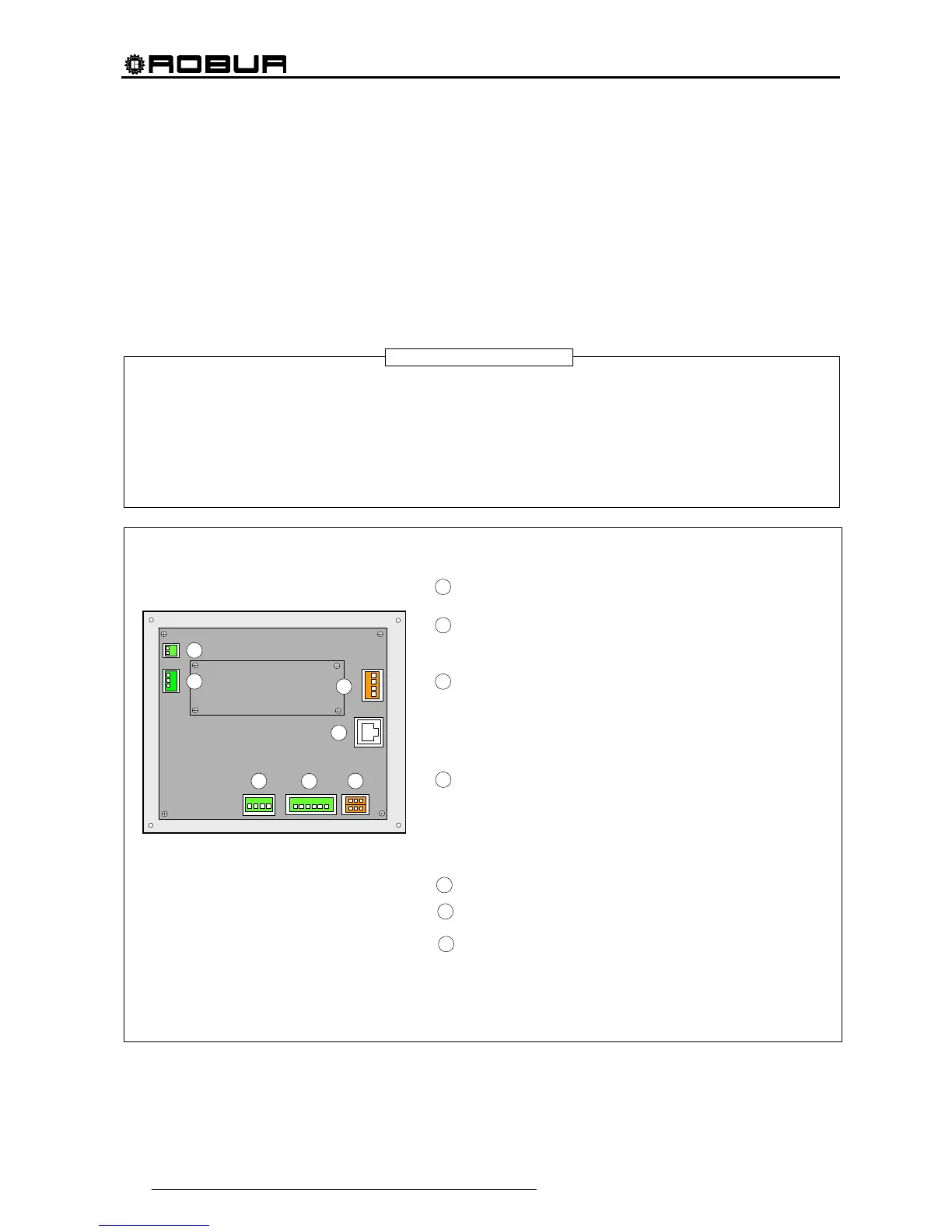
4.1.2 CONNECTING THE DIRECT DIGITAL CONTROLLER
The following connection terminals are located on the rear of the Direct Digital Controller (see Figure 13):
2-pole connector for ambient air temperature sensor, supplied as an optional accessory, if specified (see
detail A in Figure 13);
3-pole connector for alarm signal relay contacts (see detail B in Figure 13);
4-pole connector for 24 Vac power supply. Current is supplied to the DDC by a 24 Vac, 50/60Hz single
secondary transformer (see detail C in Figure 13);
6-pole connector for external operation commands, if specified (see detail D in Figure 13);
6-pole CAN-BUS connector for connecting the DDC to the units (see detail E in Figure 13).
A standard male 9-way connector (RS232 serial port) is located on the front of the Direct Digital Controller for
connection to a PC (see Figure 1 on page 7).
In particular applications, an external alarm signal may be required for high chilled water temperature and/or
for low hot water temperature, or for a general alarm that allows any anomalies in the units to be signalled.
To this end, a specific terminal with 3 contacts (see detail B in Figure 13) is provided on the rear of the Direct
Digital Controller for the activation, via a relay, of an alarm signal, such as a light, siren or other device (for
further information see Paragraphs 4.4.2.6.7 – “Temperature Alarm Setup (Master DDC only)” on page
100 and 4.4.2.4 – “Alarm output setup” on page 86.
This connection must only be used to control external equipment at very low safety voltage (SELV) up to a
maximum of 24 V and at a maximum current of 1 A. Do not connect external equipment to a 230 V supply.
Figure 13– REAR VIEW OF DIRECT DIGITAL CONTROLLER and DETAIL OF ELECTRICAL CONNECTIONS
KEY
TERMINALS FOR CONNECTION OF INTERNAL OR EXTERNAL AIR
SENSOR (NTC 10K), IF SPECIFIED (see Paragraph 4.5.3.1.4)
TERMINALS FOR CONNECTION TO EXTERNAL ALARM SYSTEMS
- terminal 1 COM
- terminal 2 NO
- terminal 3 NC
TERMINALS FOR 24 Vac FOR DIRECT DIGITAL CONTROLLER POWER
SUPPLY
Respect connection polarity
- terminal 1 24 Vac
- terminal 2 0 Vac
- terminal 3 earth
- terminal 4 not used
6-POLE CONNECTOR FOR EXTERNAL CONSENTS
(see Paragraphs 4.5.3.1.2 or 4.5.3.1.3)
- terminal 1 R (24 Vac)
- terminal 2 W (heating)
- terminal 3 Y (cooling)
- terminal 4 0 (0 Vac)
- terminal 5 NA (not connected)
- terminal 6 R (24 Vac)
CAN-BUS CABLE CONNECTION
RS232 PORT REAR CONNECTION (RJ45)
Alternative connection to front connection, for the same RS232 port
RS485 PORT CONNECTION
(see Paragraph 4.4.1.13)
- terminal 1 A (TXD/RXD+)
- terminal 2 B (TXD/RXD-)
- terminal 3 Common (connected to the system mass and earth)
- terminal 4 Cable sheath (connected to the system mass and earth)
NOTE
A
C
D
E
B
A
B
C
D
E
G
F
F
G