Direct Digital Controller
66 Direct Digital Controller fw 4.013 – Ed. 01/2013
pump. If more than one chiller of this type is assigned to a category, the switch off delay is the same for all the
water pumps of these boilers.
In this case the Delivery and return limit temperature and Auxiliary Regulator parameters are never present
for the "Progressive complement and substitution" mode as the "complement and substitution" operating
mode is not foreseen on cold generation plants.
Setting the parameters
For the description of the setting operations for these parameters, refer to the paragraph 4.4.2.6.4 “Regulation
parameters” on page 96 relative to setting the basic system part.
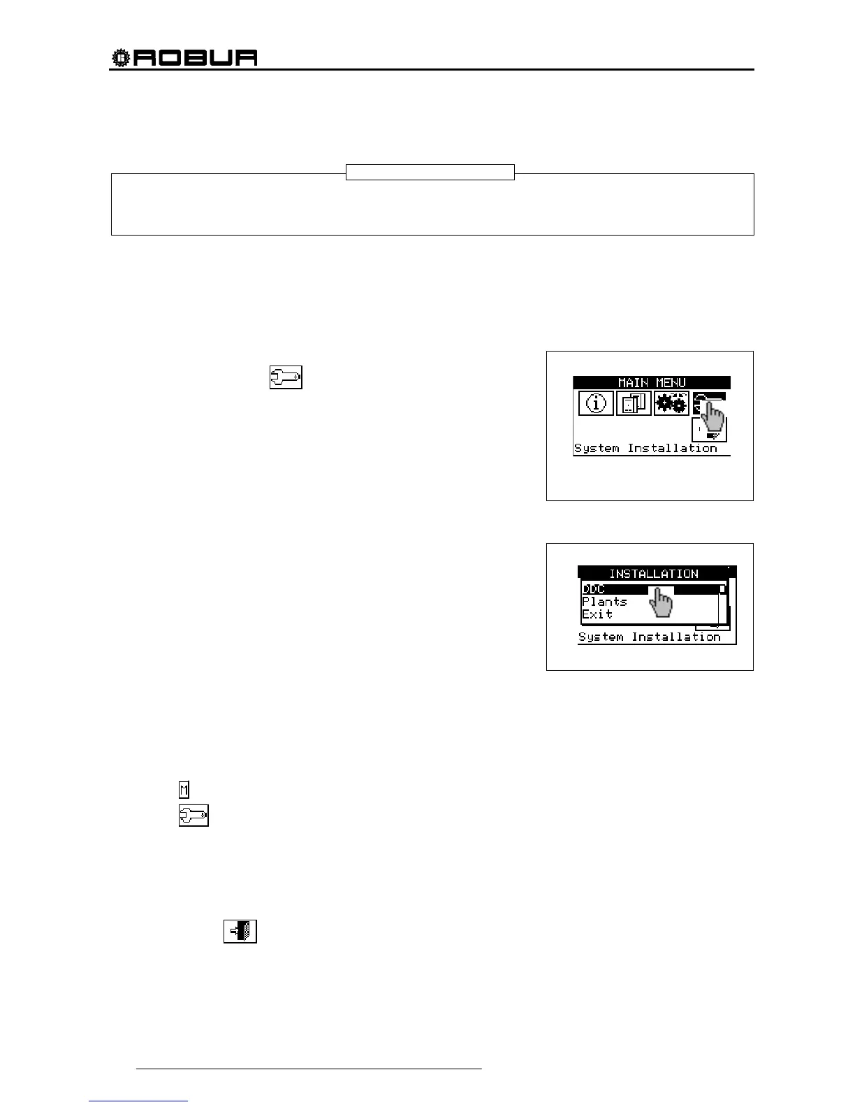
4.4 SYSTEM INSTALLATION
Only professionally qualified personnel may access this menu. To
access the menu select
from the main menu as shown in the
figure on the right, then enter, if requested, the installer password on the
numerical keypad that appears on the display.
The options available in this menu are indicated below.
4.4.1 DDC
4.4.2 PLANTS
4.4.1 DDC
To access the menu, select DDC from the drop-down menu.
4.4.1.1 Setting ID
This option allows the user to assign the ID of each Direct Digital Controller in Multi DDC plants.
For single DDC plants it is not necessary to assign an ID to the DDC, as in this case the default value of
ID=960 is assigned.
To set the ID, follow the instructions below.
1 - Select
from the initial screen to gain access to the main menu.
2 - Select
to gain access to the System installation.
3 - Enter the installer password on the numerical keypad that appears on the display.
4 - Select “DDC” from the drop-down menu.
5 - Select “Set ID” from the drop-down menu.
6 - Position the cursor on the number to the left of the text “ID value”. Press the knob: the number starts to
flash. Turn the knob to modify the value and press to confirm.
7 - To exit, select
.
8 - Repeat steps 1 to 7 for each DDC linked to the CAN BUS network and assign an ID value that is
different
from that of the other DDCs.
NOTE