14
GB
AVO-504, 505AG
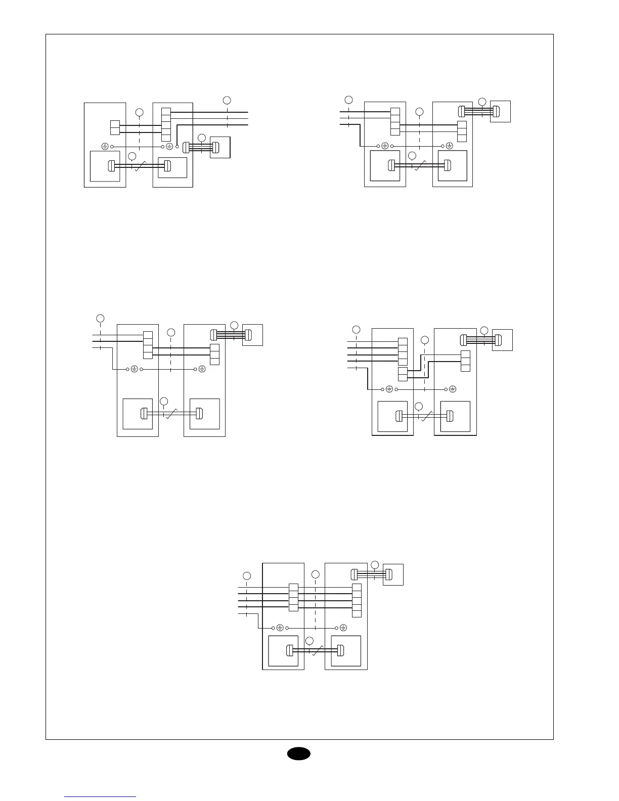
Wiring diagrams
Note:
1. Supply 3 x 2.5 mm
2. Interconnection 3 x 1 mm
3. 2-wire twisted pair
4. Control 4 x 1 mm
L
N
1
N(2)
A
1
N(2)
<<
<<
L
N
PE
230 V 50Hz
PCB PCB
OUTDOOR INDOOR
1
2
3
<<
<<
4
THERMOSTAT
AVO-507AG / F-AG
Note:
1. Supply 3 x 2.5 mm
2. Interconnection 3 x 2.5 mm
3. 2-wire twisted pair
4. Control 4 x 1 mm
<<
<<
L
N
PE
230 V 50Hz
PCB PCB
2
3
1
N(2)
<<
<<
4
L
N
1
N(2)
A
1
THERMOSTAT
OUTDOOR
INDOOR
Note:
1. Supply 3 x 4 mm
2. Interconnection 3 x 1 mm
3. 2-wire twisted pair
4. Control 4 x 1 mm
AVO-510AG / F-AG (single-phase)
L
N
1
N(2)
A
1
N
<<
<<
L
N
PE
230 V 50Hz
PCB PCB
OUTDOOR INDOOR
1
2
3
<<
<<
4
THERMOSTAT
AVO-510AG / F-AG (three-phase)
AVO-512AG / F-AG
Note:
1. Supply 5 x 2.5 mm. (510 & 512)
2. Interconnection 3 x 1 mm
3. 2-wire twisted pair
4. Control 4 x 1 mm
L1
<<
<<
PE
400 V 3N 50Hz
PCB PCB
OUTDOOR INDOOR
1
3
L2
L3
N
L1
L2
L3
N
A
1
N
1
N(2)
<<
<<
4
THERMOSTAT
2
AVO-516AG / F-AG
Note:
1. Supply 5 x 2.5 mm. (Indoor unit power supply can be provided by
interconnection with the outdoor unit or independently)
2. 2-wire twisted pair
3. Control 4 x 1 mm
L1
<<
<<
PE
400 V 3N 50Hz
PCB PCB
OUTDOOR INDOOR
1
2
L2
L3
N
L1
L2
L3
N
<<
<<
3
THERMOSTAT
1
L1
L2
L3
N
A