EasyManua.ls Logo

Roca BCH-7 User Manual

Roca BCH-7
48 pages
To Next Page IconTo Next Page
Page #1 background imageLoading...
Page #1 background image
1
Model BCH
horizontal packaged
air to air heat pump
Technical information
Ref.: N-26844 0700
Clima Roca York S.L. is participating in the EUROVENT Certification Programme.
Products are as listed in the EUROVENT Directory of Certified Products,
in the program
AC1, AC2 and AC3.
EUROVENT
CERTIFIED PERFORMANCE
CGM-97/013
ACCORDING TO ISO 14001 STANDARDS
ER-028/1/91
ACCORDING TO ISO 9001 STANDARDS
Question and Answer IconNeed help?

Do you have a question about the Roca BCH-7 and is the answer not in the manual?

Roca BCH-7 Specifications

General IconGeneral
BrandRoca
ModelBCH-7
CategoryHeat Pump
LanguageEnglish

Summary

Technical Information

General Information

General Description & Nomenclature

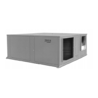
Overview of the BCH heat pump's general characteristics and naming conventions.

Control System Overview

Details on the electronic module, balance point, safeties, defrost, and control panel.

Technical Specifications

Mechanical Specifications & Physical Data

Covers compressor type, coils, casing, fans, and physical dimensions.

Nominal Features, Test Conditions, Correction Factors, Flow-Rates

Key performance data including capacities, test parameters, and flow rate adjustments.

Sensitive Cooling Capacities

Fan Performance Data

Outdoor & Indoor Fan Performance

Detailed performance data for both outdoor and indoor fans.

Installation Instructions

Installation Guidelines, Safety & Location

Covers general installation, environmental protection, warnings, transport, and location.

Mounting, Connections & Air Ducts

Details on unit attachment, drain connections, clearances, and air ducting.

Electrical Installation

Start-Up Procedure & Electrical Characteristics

Steps for start-up and table of electrical characteristics for each model.

Utilization Limits and Control Settings

Voltage, Temperature Limits, Sensors & Control Logic

Defines operational limits, sensor functions, and control logic parameters.

Control Module Operation & Connections

Pin Functions, Leds & Module Details

Description of module pins, LEDs, and internal connections.

Module Indicators & Autodiagnosis

Module Overview & LED Autodiagnosis

Explains the module layout and the meaning of LED indications.

Operating Sequences

Summer Cycle Operation

Detailed description of the summer operating cycle.

Winter Cycle Operation

Detailed description of the winter operating cycle.

Special Operating Conditions

Defrost, Low Temp & Emergency Heat

Describes defrost cycle, low-temperature operation, and emergency heat.

Operating Instructions

Thermostat Setup and Mode Selection

Instructions for setting up the thermostat and selecting operating modes.

Cooling, Heating, Automatic & Emergency Modes

Detailed explanation of various operating modes on the thermostat.

Fan Settings & Day/Night Selection

Configuration of fan speed and day/night temperature settings.

Graphic Information & Maintenance

Graphic Information & Maintenance Procedures

Information on display panel icons and maintenance tasks like cleaning.

General Dimensions

BCH-7, 10 Dimensions

Detailed dimensional drawings and measurements for BCH-7 and BCH-10 models.

BCH-12, 15 & 20 Dimensions

Detailed dimensional drawings and measurements for BCH-12, 15, and 20 models.

BCH-25 & 30 Dimensions

Detailed dimensional drawings and measurements for BCH-25 and BCH-30 models.

Wiring Diagrams

BCH-7 Wiring Diagram

Electrical wiring schematic for the BCH-7 model.

BCH-10, 12, 15 Wiring Diagrams

Electrical wiring schematics for BCH-10, 12, and 15 models.

BCH-20 Wiring Diagrams

Electrical wiring schematics for the BCH-20 model.

BCH-25 & 30 Wiring Diagrams

Electrical wiring schematics for BCH-25 and BCH-30 models.

Power Diagrams

BCH-7 Power Diagram

Power circuit diagram for the BCH-7 model.

BCH-10, 12, 15 Power Diagrams

Power circuit diagrams for BCH-10, 12, and 15 models.

BCH-20 Power Diagrams

Power circuit diagrams for the BCH-20 model.

BCH-25 & 30 Power Diagrams

Power circuit diagrams for BCH-25 and BCH-30 models.

Control Diagrams

BCH-7, 10, 12, 15 Control Diagrams

Control circuit diagrams for BCH-7, 10, 12, and 15 models.

BCH-20 Control Diagrams

Control circuit diagrams for the BCH-20 model.

BCH-25 & 30 Control Diagrams

Control circuit diagrams for BCH-25 and BCH-30 models.

Optional Accessories

Filters and Electric Heaters

Details on optional filters and electric heaters for the heat pump.

Filter Rack Details

Dimensions and pressure drop data for filter racks.

Air Filter Details

Dimensions and pressure drop data for air filters.

Indoor Electric Heater Details

Specifications and dimensions for indoor electric heaters.

Duct Electric Heater Details

Specifications and dimensions for duct electric heaters.

Related product manuals