Index
General 5
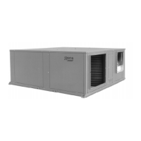
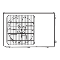
- General description 5
- Nomenclature 5
- Control 5
Technical specifications 5
- Mechanical specifications 5
- Physical data 6
- Nominal features 7
- Test conditions 7
- Correction factors 7
- Nominal flow-rates 7
- Sensitive cooling capacities 8 - 9
- Outdoor fan performance 10
- Indoor fan performance 10
Installation instructions 11
- General 11
- Protection of the environment 11
- Warning signs 11
- Transport 11
- Location 11
- Attaching unit 12
- Drain connections 12
- Clearances 12
- Air ducts 12
- Air intake and discharge orientations 13
- Variations to be performed at jobsite 13
Electrical installation 14
- Start-up procedure 14
- Electrical characteristics 14
- Utilization limits 15
- Balance point adjustment 15
- Logic module 15
- Discharge sensor 15
- Outdoor sensor 15
- Liquid sensor 15
- Balance point 15
- Timer 15
- Stoppage of inferior fan during defrost 15
- Delayed switch-off interior fan 16
- Other 16
Operation 16
- Summer cycle 16
- Winter cycle 16
- Detail module internal connections
with exits to the connector 16
- Function of the pins 16
- Actions according to state of the probe 16
- Module 17
- Indications led autodiagnosis 17
- Operating sequences 18 - 19
- Defrost cycle (timer) 20
- Operating at -15°C 20
-
Operation on emergency heat 20
- Other safety features of the electric circuit 20
- Compressor crankcase oil heater 20
- Before finalising the installation 20
Operating instructions 21
- General instroduction 21
- DSL ambient thermostat for 610 heat pump 21
- Operation and start up 21
- Graphic information 24
Maintenance 24
- Cleaning of filters 24
- Cleaning outdoor coil 24
- Priming the dreinage siphon 24
- Indoor unit discharge ducts 24
General dimensions 25 - 27
Wiring diagrams 28 - 41
Optional accessories 42
- Filter rack with filter 43
- Air filter 44
- Indoor electric heaters RH 45
- Duct electric heaters RC-220 46
Page
Page