Do you have a question about the Rocket Espresso R58 and is the answer not in the manual?
Locate and remove four Phillips head screws around the reservoir to detach the cover.
Loosen or fully remove the 7mm screws located on the bottom of the machine.
Loosen four inward-facing screws, two front and two back, using a 7mm wrench.
After loosening the internal screws, the machine panels can be carefully removed.
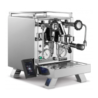
This document outlines the process for removing the housing from a Rocket espresso machine, specifically using a Rocket R58 model as an example. The instructions are designed to be applicable to various Rocket machines, providing a general guide for users who need to access the internal components of their device for maintenance, repair, or modification. The primary function of this guide is to enable users to safely and effectively dismantle the external casing of their espresso machine, granting access to the intricate internal mechanisms such as the boiler, pump, and various plumbing.
The process begins with an introduction that sets the context for the task, emphasizing the general applicability of the instructions while noting the specific model used for demonstration. This ensures that users with different Rocket machines can still follow along, understanding that minor variations might exist but the core steps remain consistent. The guide immediately lists the necessary tools: a 7mm wrench and a small Phillips head screwdriver. This upfront declaration of tools is crucial for users to prepare adequately before starting the disassembly, preventing interruptions and ensuring a smooth workflow.
Step 1 focuses on the initial removal of the top panel. This involves two main actions: first, removing the reservoir cover, which typically sits on top of the machine and protects the water reservoir. Second, the reservoir itself needs to be removed. This step is critical as the reservoir often obstructs access to the screws holding the top panel in place. Once the reservoir is out, the user is directed to locate four small Phillips head screws situated in the corners around where the reservoir was. These screws secure the top panel to the machine's frame. The instructions explicitly state to use the Phillips head screwdriver for this task. After these screws are removed, the top panel can be lifted off, revealing the internal layout of the machine. The guide includes an image illustrating what the machine should look like after the top panel has been successfully removed, providing a visual confirmation for the user. This visual aid is invaluable for ensuring the user is on the right track and understands the expected outcome of each step.
Step 2 addresses the removal or loosening of screws located on the bottom of the machine. The guide offers a choice: either completely remove these screws or simply loosen them. The author's personal preference is to loosen them, suggesting that this might be sufficient for the subsequent steps and could potentially simplify reassembly. A significant piece of advice is provided here: if the user chooses to lay the machine on its side to access the bottom screws, it is highly recommended to place a towel underneath. This precaution is vital for preventing scratches or damage to the machine's polished sides, which are often made of stainless steel and susceptible to cosmetic imperfections. The instructions specify using the 7mm wrench for these screws, indicating that they are likely hex-head screws, distinct from the Phillips head screws used on the top panel. An image is provided, clearly marking the locations of these 7mm screws on the bottom of the machine, further aiding the user in identifying the correct fasteners.
Step 3 delves into the removal of "inverse screws." These screws are described as facing inward, towards the interior of the machine, rather than outward. They are located in four positions: two in the back-left and back-right corners, and two in the front-left and front-right corners. The guide notes that these screws might require "small micro turns" to undo, implying they could be tightly secured or have a fine thread. A strong recommendation is given not to fully remove these screws, as they can be challenging to reinsert due to the numerous small turns required. Instead, the user is advised to loosen them just enough for the panels to come apart. This advice is practical and aims to save the user time and frustration during reassembly. The 7mm wrench is again specified for these screws, indicating consistency in the type of fasteners used for the main housing components. The guide includes images to show the location of these inverse screws, specifically highlighting the two in the back and the two in the front, offering clear visual cues for identification.
Finally, Step 4 concludes the housing removal process. Once all the specified screws (top panel Phillips head, bottom 7mm, and inverse 7mm) have been loosened or removed as instructed, the user should be able to take the side panels off the machine. This step signifies the successful completion of the primary objective: gaining access to the machine's internal components. The guide implies that the side panels, once detached, can be carefully lifted away, fully exposing the boiler, plumbing, wiring, and other internal mechanisms. An image is provided showing the machine with its panels removed, offering a final visual confirmation of the expected state.
Throughout the document, the language is clear, concise, and instructional, using direct commands to guide the user through each action. The inclusion of specific tool requirements for each type of screw (Phillips head vs. 7mm wrench) is a thoughtful detail that prevents confusion. The emphasis on preventing damage, such as using a towel when laying the machine on its side, highlights a user-centric approach to maintenance. The advice regarding not fully removing the inverse screws is another example of practical guidance aimed at simplifying the overall process for the user. The consistent use of images to illustrate screw locations and the appearance of the machine at various stages is a strong feature, enhancing comprehension and reducing the likelihood of errors. This instructional guide effectively serves its purpose by breaking down a potentially complex task into manageable, easy-to-follow steps, empowering users to perform housing removal on their Rocket espresso machines with confidence.
| Type | Espresso Machine |
|---|---|
| Manufacturer | Rocket Espresso |
| Model | R58 |
| Boiler Type | Dual Boiler |
| Pump Type | Rotary Pump |
| PID Temperature Control | Yes |
| Water Reservoir Capacity | 2.5 liters |
| Body Material | Stainless Steel |
| Weight | 29 kg |
| Power | 1400 W |
| Water Source | Reservoir or Plumbed |
| Pre-infusion | Yes |
| Pressure Gauge | Yes |
| Portafilter Size | 58 mm |
| Portafilter | Commercial |
| Voltage | 220-240V |