Do you have a question about the Rockford Fosgate 250 sERIES and is the answer not in the manual?
| Brand | Rockford Fosgate |
|---|---|
| Model | 250 sERIES |
| Category | Amplifier |
| Language | English |
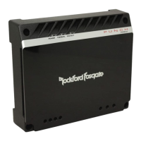
Overview of Rockford Fosgate's 250 Series Power amplifiers, highlighting their advanced technologies like Trans•nova, DIABLO, and TOPAZ.
Patented circuit using low voltage for audio signal, improving linearity, efficiency, and reliability.
Dynamically Invariant A-B Linear Operation circuit reducing high-frequency distortion and improving stability.
Tracking Operation Pre-Amplifier Zone circuitry for improved isolation and elimination of ground loop noise.
Manufacturing process combining discrete components and integrated circuitry for compactness, ruggedness, and heat dissipation.
Internal active crossovers configurable for high-pass, low-pass, and full range operation with precise frequency adjustments.
Convenient output for daisy-chaining amplifiers, providing constant Full Range stereo output or selectable HP/LP output.
Differential input circuitry for enhanced noise rejection in signal transmission over long cables.
Analog computer process for maximizing safe output power by precisely controlling current to MOSFETs.
Utilizes MOSFETs for advantages like thermal stability, switching speed, low output impedance, and wider bandwidth linearity.
Power supply design minimizing heat generation through toroidal transformer and direct lead routing.
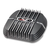
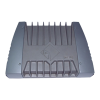
Dissipates heat generated by amplifier circuitry, offering 30% improved cooling over conventional designs.
Conceal wiring and input cables for a clean, "stealth" look.
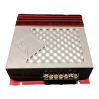
Heavy-duty, gold-plated terminal block connectors accepting 8 to 18 AWG wire, immune to corrosion.
Dual gold-plated connectors accommodating up to two 8 AWG wires for maximum input current capability.
Gold-plated spade terminal for auto power or remote turn-on of the amplifier.
Industry standard gold-plated RCA jacks for easy signal level input, resistant to signal degradation.
Dissipates heat generated by amplifier circuitry, offering 30% improved cooling over conventional designs.
Conceal wiring and input cables for a clean, "stealth" look.
Heavy-duty, gold-plated terminal block connectors accepting 8 to 18 AWG wire, immune to corrosion.
Dual gold-plated connectors accommodating up to two 8 AWG wires for maximum input current capability.
Gold-plated spade terminal for auto power or remote turn-on of the amplifier.
Industry standard gold-plated RCA jacks for easy signal level input, resistant to signal degradation.
Lists essential tools required for installing the Punch 250x2 and 250m amplifiers.
Recommendations for mounting amplifiers in the trunk for optimal heat dissipation.
Guidelines for mounting amplifiers in the passenger compartment, emphasizing proper ventilation.
Warning against mounting amplifiers in the engine compartment due to warranty voiding and heat issues.
Instructions on how to alter the crossover point by changing the resistor value on the XCard.
Diagram for power connection option 1 for the 250x2 amplifier.
Diagram for power connection option 2 for the 250x2 amplifier.
Configuration for stereo and mono operation of the amplifier.
Setup for bridged operation of the amplifier, connecting speakers to specific terminals.
Specific configuration for EZ-Bridged operation, detailing input and phase switch settings.
Guide on connecting the Balanced Line Transmitter (BLT) to the amplifier for improved signal quality.
Diagram for power connection option 1 for the 250m amplifier.
Diagram for power connection option 2 for the 250m amplifier.
Diagram illustrating a 250W system setup with specific component connections and crossover frequencies.
Diagram illustrating a 500W system setup with specific component connections and crossover frequencies.
Diagram illustrating a 750W system setup with specific component connections and crossover frequencies.
Diagram illustrating a 1000W system setup with specific component connections and crossover frequencies.
Accessory that converts RCA signals to balanced signals, improving sound quality by reducing noise.
LED array monitoring amplifier performance, including power, signal level, and thermal condition.
Diagnosis and remedies for amplifier failure to power on, checking voltage and grounding.
Diagnosis and remedies for lack of sound when the amplifier is powered on, checking inputs and connections.
Troubleshooting steps for low or distorted speaker output, checking gain, source, and wiring.
Diagnosis and remedies for amplifier noise or turn-on pop, checking signal sources and remote turn-on.
Troubleshooting for lack of output from the Pass-Thru jacks, checking connections and source units.
Diagnosing and resolving low or distorted output specifically from the amplifier's Pass-Thru connection.
Introduction to troubleshooting car audio systems, emphasizing signal optimization and noise reduction.
Explains common sources of electrical interference in car audio systems: power line, power supply, and inductive.
A systematic troubleshooting methodology for car audio systems.
Procedure to test the deck by temporarily relocating it to isolate noise sources.
Guidance on integrating signal processors into the system one by one to identify noise issues.
Concluding remarks on system setup, component isolation, grounding, and cable selection for noise reduction.