Do you have a question about the Rockford Fosgate Prime R600-5 and is the answer not in the manual?
| Channels | 5 |
|---|---|
| Power Output (RMS) | 600 Watts |
| Frequency Response | 20 Hz - 20 kHz |
| Subwoofer Frequency Response | 20 Hz - 200 Hz |
| Signal-to-Noise Ratio | > 100 dB |
| Crossover | High-pass / Low-pass |
| Crossover Slope | 12 dB/octave |
| Crossover Type | Variable |
| Dimensions | 2.0" x 6.8" x 13.3" (5.1cm x 17.3cm x 33.8cm) |
| Input Sensitivity | 150 mV to 4 V |
| Bass Boost | 0dB to +12dB @ 45Hz |
| RMS Power @ 4 Ohms | 50 Watts x 4 + 200 Watts x 1 |
| Bridged RMS Power @ 4 Ohms | 150 Watts x 2 |
| Total Harmonic Distortion (THD) | < 1% |
Continuous exposure to sound pressure levels over 100dB may cause permanent hearing loss. Use common sense.
Highlights critical safety warnings and cautions for installation and use to prevent injury or unit damage.
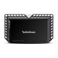
Blue LED indicator for unit status, illuminates when the unit is turned on.
Red LED indicator for short circuit or low impedance detection. Shuts down amplifier automatically.
Narrow band bass boost adjustment at 45Hz, selectable between 0dB, +6dB, and +12dB.
Built-in 12dB/octave Butterworth filter with adjustable crossover point from 50Hz to 250Hz.
Selectable switch for High-Pass (HP), All Pass (AP), or Low-Pass (LP) operation.
Input gain control to match output levels from various source units.
Industry standard RCA jacks for signal level input, nickel-plated to resist corrosion.
Allows selection of output phase between 0° and 180° for the subwoofer channel.
Built-in 12dB/octave Butterworth filter for sub channel, adjustable from 40Hz to 130Hz.
Variable bass level control from 0dB to +12dB centered at 45Hz.
Remote control for amplifier output level when connected to the dash or center console.
Nickel-plated clamp wire connectors for power and ground, accommodating fork or ring connectors.
Nickel-plated clamp wire connector for remote turn-on/turn-off function.
ATC fuses for protection, easily accessible for replacement.
Heavy duty, nickel-plated clamp connectors for speakers.
Lists tools and materials needed for installation, including wire strippers, crimpers, and connectors.
Emphasizes disconnecting the battery, reading the manual, and handling wires safely to prevent injury or damage.
Warns against mounting in the engine compartment as it voids the warranty.
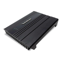
Suggests vertical or inverted mounting for adequate cooling in the trunk.
Requires sufficient air gap for cooling, especially under seats (1 inch minimum).
Guidelines for routing RCA, power, and ground wires to prevent noise induction and short circuits.
Steps for connecting the positive power wire to the amplifier and battery, including fusing.
Instructions for preparing and connecting the ground wire to the amplifier and chassis.
Steps for connecting the remote turn-on wire to the amplifier and a switched 12V source.
Securing the amplifier and connecting RCA cables for audio input.
Instructions for connecting speaker wires to terminals, ensuring polarity and avoiding chassis grounding.
Performing a final check of all wiring for accuracy, frayed wires, and loose connections.
Specifies minimum recommended impedance loads for stereo and bridged configurations.
Guide to setting input gain to match source unit volume, minimizing noise and distortion.
Explanation of HP, AP, and LP crossover modes and setting the variable crossover points.
Details on the narrow band bass boost at 45Hz and the sub channel bass control.
Function of the phase switch for changing output polarity between 0° and 180°.
How to use the remote control to adjust amplifier output level from the dash or console.
Verifies power, fuse, ground, and voltage connections if the POWER light is off.
Explains the Protect light indicates a short circuit or low impedance at speaker connections.
Steps to verify RCA input connections and test for audio output.
Solutions for turn-on pop, including using delay modules or alternative voltage sources.
Methods to eliminate engine noise, such as wire routing, bypassing components, and grounding.
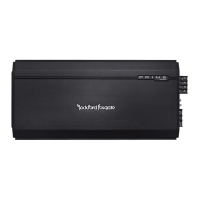
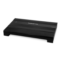
Details continuous power output at various impedances and physical dimensions of the amplifier.
Lists amplifier fuse rating, external fuse rating, and weighted signal-to-noise ratios.
Describes amplifier topology, crossover slopes, and frequency response ranges.
Covers signal voltage adjustment, protection features, and punch bass control specifics.
Details phase settings, input impedance, operating voltage, CMRR, damping factor, and THD+N.
Specifies warranty duration for different product types and what is covered by the warranty.
Details what is not covered by the warranty and limits on implied warranties.
Instructions on how to get service, obtain RA#, and information on EU warranty requirements.