Do you have a question about the Rockford Fosgate Punch P4004 and is the answer not in the manual?
| Channels | 4 |
|---|---|
| RMS Power Output (4 Ohm) | 50W x 4 |
| RMS Power Output (2 Ohm) | 100W x 4 |
| Bridged RMS Power (4 Ohm) | 200W x 2 |
| Total Power Output | 400W |
| Frequency Response | 20 Hz - 20 kHz |
| Fuse Rating | 40A |
| Total Harmonic Distortion (THD) | <0.05% |
| Crossover | 12dB/Octave LP/HP |
| Input Sensitivity | 150mV to 4V |
Important instructions to prevent injury or unit damage during installation and operation.
Illuminates when the unit is on and indicates output signal level.
Indicates short circuit or low impedance; shuts down amplifier automatically.
Indicates overheating; shuts down amplifier to cool.
Dissipates heat generated by the amplifier's circuitry.
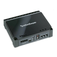
Heavy-duty, nickel-plated connectors for speaker wire (8-18 AWG).
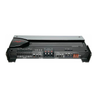
Adjusts low-frequency boost for bass enhancement.
Adjusts input gain to match source unit output levels.
12dB/octave filter for HP, AP, or LP operation (40Hz-400Hz).
Industry-standard jacks for easy signal level input.
Allows daisy-chaining additional amplifiers without extra RCA cables.
Connects for remotely turning the amplifier on/off with +12V DC.
Nickel-plated connectors for power and ground wires (up to 4 AWG).
ATC fuses for easy access and replacement.
Switches inputs for 2-channel mode or 4-channel output.
Vehicle considerations, planning wire routing, and tool requirements.
Recommendations for mounting amplifier in engine, trunk, or passenger compartments.
Importance of checking vehicle's battery and charging system for amplifier load.
Step-by-step guide for connecting power, ground, and signal wires.
Mounting and installation of the remote bass control.
Procedure for setting the amplifier's input gain for optimal volume.
Setting the HP, AP, or LP crossover points for frequency filtering.
Verifying power, ground, and voltage connections for proper operation.
Diagnosing issues indicated by Protect or Thermal LEDs.
Troubleshooting no audio output issues, checking RCA connections.
Resolving turn-on pop noise with delay modules or relays.
Identifying and eliminating engine noise interference in the audio system.