Programming and Parameters 3-5
Display Group (continued)
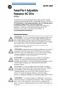
d012 [Control Source]
Related Parameter(s): P036, P038, A051, A052
Displays the active source of the Start Command and Speed Command which are normally defined
by the settings of P036 [Start Source] and P038 [Speed Reference] but may be overridden by digital
inputs. Refer to the flowcharts on pages 1-17 and 1-18 for details.
Values Default Read Only
Min/Max: 0/9
Display: 1
Start Command Bit 0
0 = Keypad
1 = 3-Wire
2 = 2-Wire
3 = 2-Wire Level Sensitive
4 = 2-Wire High Speed
5 = RS485 (DSI) Port
9 = Jog
Speed Command Bit 1
0 = Drive Potentiometer
1 = A069 [Inter
nal Freq]
2 = 0-10V Input/Remote Potentiometer
3 = 4-20mA Input
4 = A070-A073 [Preset Freq x]
(A051 - A052 [Digital Inx Sel] must be set to 4)
5 = RS485 (DSI) Port
9 = Jog Freq
Reserved Bit 2
Reserved Bit 3
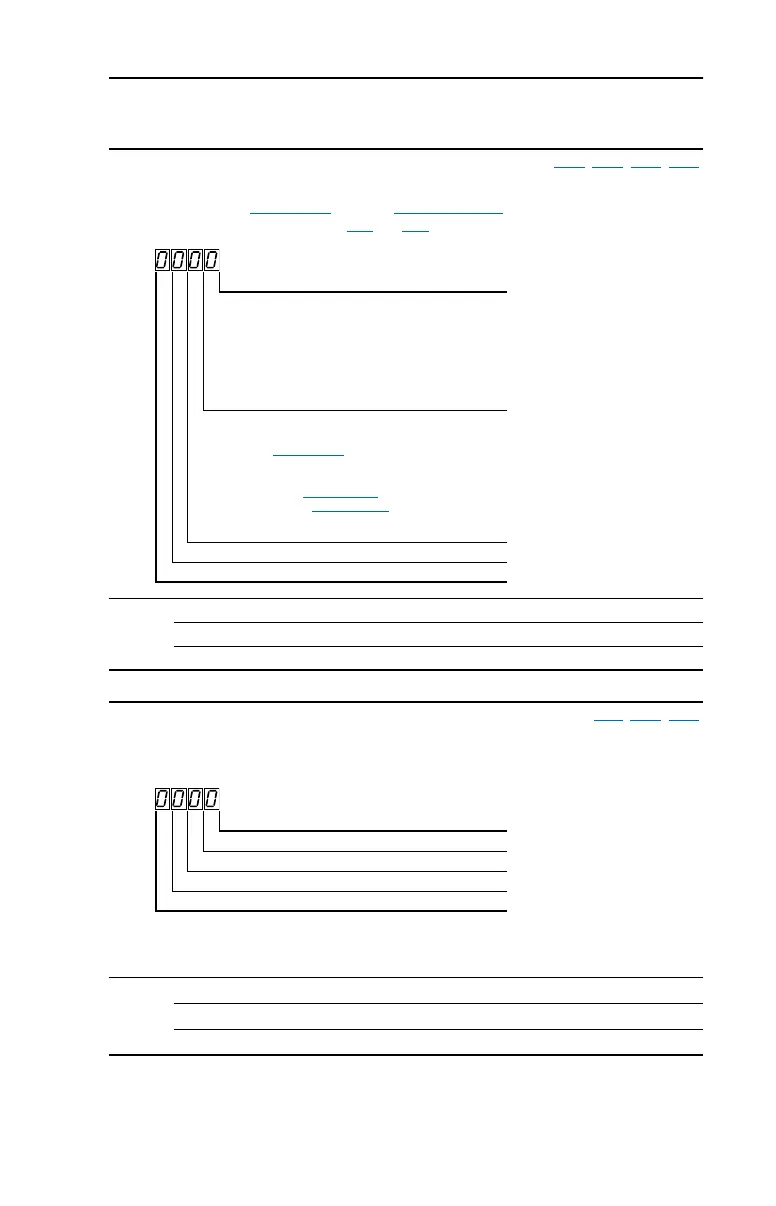
d013 [Contrl In Status]
Related Parameter(s): d002, P034, P035
Status of the control terminal block control inputs.
Important: Actual control commands may come from a source other than the control terminal block.
Values Default Read Only
Min/Max: 0/1
Display: 1
1 = Input Present, 0 = Input Not Present
Start / Run FWD Input (I/O Terminal 02) Bit 0
Direction / Run REV Input (I/O Terminal 03) Bit 1
Stop Input
(1)
(I/O Terminal 01) Bit 2
(1)
The stop input must be present in order to start the drive.
When this bit is a 1 the drive can be started.
When this bit is a 0 the drive will stop.
Reserved Bit 3
userman.book Page 5 Friday, June 21, 2002 2:48 PM
 Loading...