Rockwell Automation Publication 440R-UM013F-EN-P - July 2021 71
Chapter 11 Troubleshooting
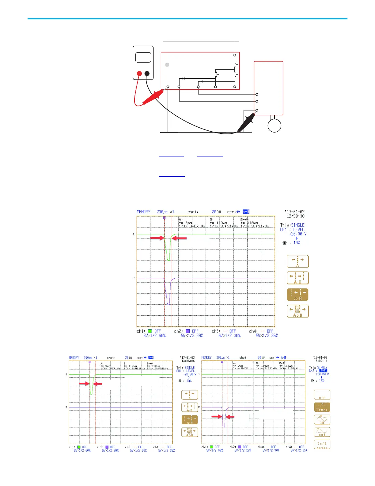
Figure 80 - Continuity Test of the Voltage Supply Common Connection
The OSSD test pulses of the DIS safety relay, as viewed by an oscilloscope, are
shown in Figure 81 and Figure 82. Most often, the main transistor triggers the
scope; this test pulse appears on all four terminals simultaneously. The main
transistor pulses are about 110 µs wide. Each channel is tested individually as
shown in Figure 82
. The individual pulses are about 50 µs wide. These pulse
widths are provided for informational purposes; the pulses cannot be turned
OFF or adjusted.
Figure 81 - OSSD Main Transistor Test Pulses
Figure 82 - OSSD Channel Transistor Test Pulse
34 44 14 24
S2
4
S1
A1
A2
OUT
<1
Ohms
DMM
24V common
24V DC supply
PowerFlex 525
AC Drive
Motor
50 µs
50 µs
Terminal 14, 34
Terminal 24, 44
 Loading...


