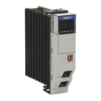
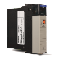
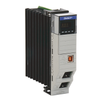
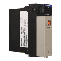
Do you have a question about the Rockwell Automation Allen-Bradley 1756-EN2TR and is the answer not in the manual?
Explains warning symbols like WARNING, ATTENTION, SHOCK HAZARD, BURN HAZARD, ARC FLASH HAZARD, and informative icons.
Describes electronic keying options (Compatible Module, Disable Keying, Exact Match) for preventing incorrect device usage.
Details enabling and disabling explicit protected mode on modules to prevent configuration changes.
Explains enabling and disabling explicit protected mode for redundant adapter pairs.
Introduces CIP Security as a standard for secure data transport and authentication on EtherNet/IP networks.
Explains DLR for detecting, managing, and recovering from faults in ring networks.
Illustrates using rotary switches to set the IP address and discusses BOOTP/DHCP fallback.
Details IP address considerations and steps for configuring redundant 1756-EN4TR adapter pairs.
Explains conditions that trigger switchovers between primary and secondary redundant adapters.
Provides step-by-step instructions for configuring a 1756-EN4TR redundant adapter pair using Studio 5000.
Details disabling/enabling Ethernet ports using FactoryTalk Linx Network Browser.
Describes disabling/enabling Ethernet ports using the Port Configuration tab in Studio 5000.
Details disabling CIP Security ports using the FactoryTalk Linx Network Browser checkbox.
Explains disabling CIP Security ports using a MSG instruction and specific controller tags.
Explains how to disable the 1756-EN4TR module webpages using a MSG instruction.
Explains how to enable the 1756-EN4TR module webpages using a MSG instruction and specific tags.
Details disabling SNMP using a MSG instruction and specific controller tags.
Explains enabling SNMP using a MSG instruction and specific controller tags.
Details the status and state of indicators for single-port modules like LINK, OK Status, and Network Status.
Explains the status and state of indicators for dual-port modules, including Link Status, SD card, and PRP.
| Product Type | Ethernet Communication Module |
|---|---|
| Series | 1756 |
| Protocol | Ethernet/IP |
| Number of Ports | 2 |
| Port Type | RJ45 |
| Data Rate | 10/100 Mbps |
| Vibration | 5 g @ 10-500 Hz |
| Shock (operating) | 30 g |
| Shock (nonoperating) | 50 g |
| Operating Temperature | 0 to 60 °C (32 to 140 °F) |
| Storage Temperature | -40 to 85 °C (-40 to 185 °F) |
| Relative Humidity | 5 to 95% non-condensing |
| Certifications | CE |
| Power Supply | 24VDC |


 Loading...