Rockwell Automation Publication 2711R-IN001B-EN-P - September 2022 9
PanelView 800 HMI Terminals Installation Instructions
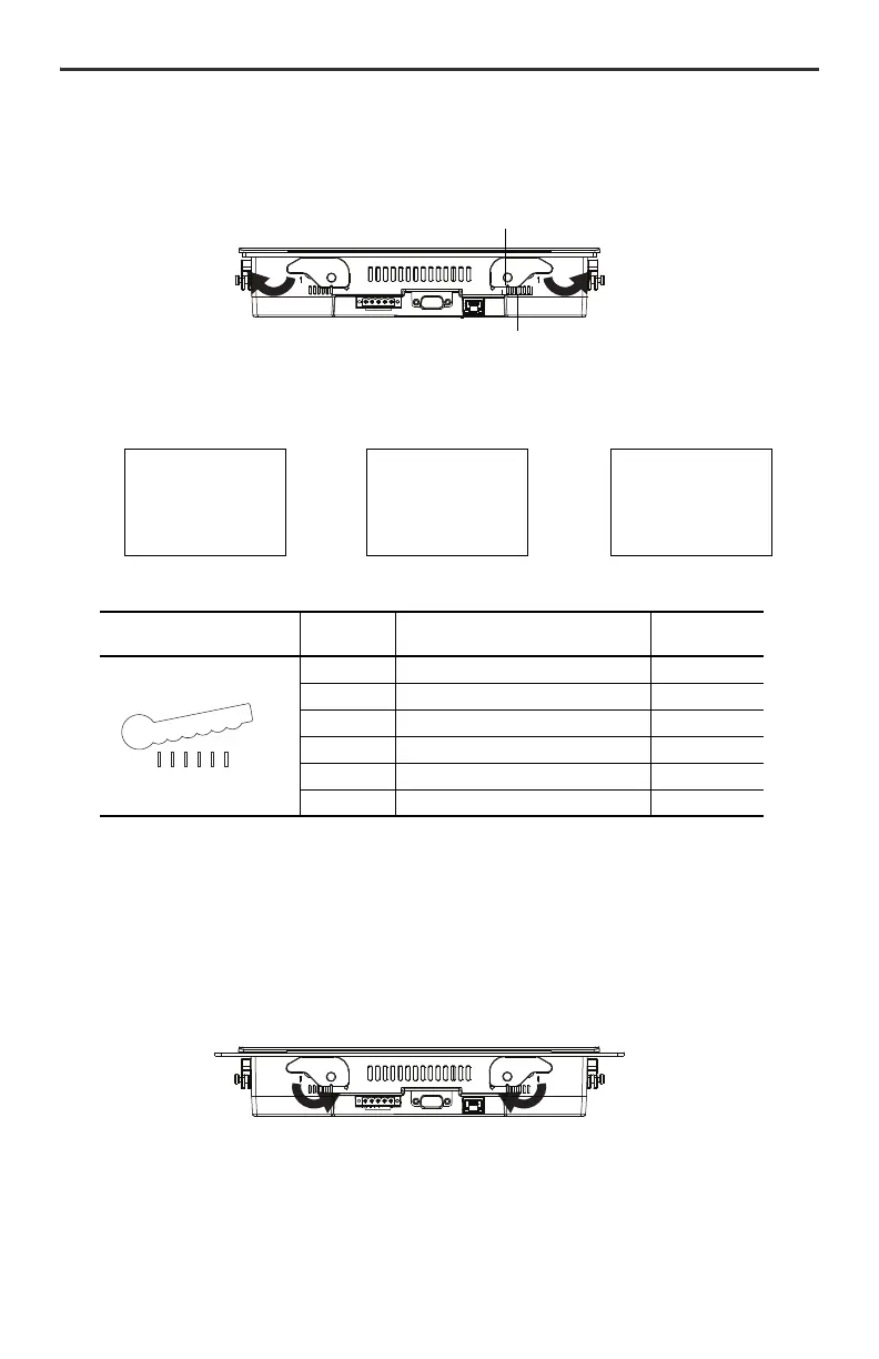
6. Rotate each lever in direction indicated until it is in the final latch position.
Follow the latching sequence for the optimum terminal fit.
Use this table as a guide to provide an adequate gasket seal between the terminal and the panel.
Remove the PanelView 800 Terminal from the Panel
Follow these steps to remove the terminal from the panel.
1. Disconnect power to the terminal.
2. Release the mounting lever by rotating it in the direction indicated, slide it to the bottom of the mounting
slot, and remove it.
Terminal Markings for
Alignment
Lever
Position
Panel Thickness Range Typical Gauge
1 1.52…2.01 mm (0.060…0.079 in.) 16
2 2.03…2.64 mm (0.08…0.104 in.) 14
3 2.67…3.15 mm (0.105…0.124 in.) 12
4 3.17…3.66 mm (0.125…0.144 in.) 10
5 3.68…4.16 mm (0.145…0.164 in.) 8/9
6 4.19…4.75 mm (0.165…0.187 in.) 7
Rotate until notch in lever aligns with
proper alignment mark on terminal.
Notch
Six alignment marks
Latching sequence for 2711R-T4T Latching sequence for 2711R-T7T Latching sequence for 2711R-T10T
14
32
14
3
2
56
14
32
57
86
6
1
1
2
3
4
5
6
 Loading...


