Rockwell Automation Publication 42G-TD001C-EN-P - June 2022 5
Series 9000 Photoelectric Sensors Specifications Technical Data
Cordsets and Accessories
Sensor User Interface
(1) Transmitted beam receivers do not have a flashing (low margin) state.
(2) The sensors timing can be set as short (0…1.5 s) or long (0…15 s).
Description Cat. No.
Cordsets
AC micro QD, straight, 4-pin, 2 m (6.5 ft)
889D-F4AEA-2
Mini QD, 1.8 m (6 ft) 5-pin
889N-F5AF-6F
Mini QD, 2 m (6 ft) 4-pin 889N-F4AF-6F
Mounting bracket
30 mm (1.2 in.) swivel/tilt
60-2439
Heavy-duty impact
60-2702
Spare reflector,
corner cube
76 mm (3 in.) diameter with mounting hole
92-39
32 mm (1.25 in.) diameter with mounting hole 92-47
Extended range lens assembly [260 °C (500 °F)]
60-1844
60-2559
Fiber-optic cable lens extender 60-2738
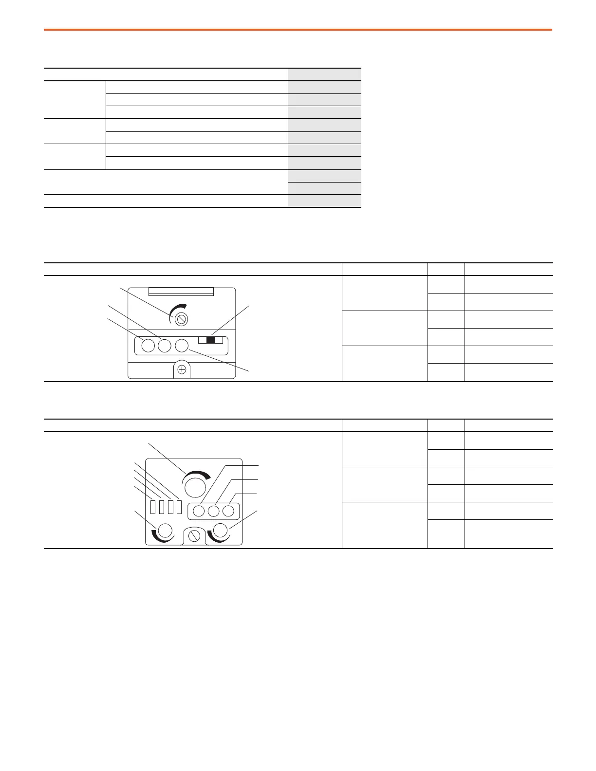
Table 7 - Standard Sensors
42GRx Versions — Top View Detail Status Indicator Color State Status
Red
OFF Margin < 2.5X
ON Margin > 2.5X
Green
OFF Output is de-energized
ON Output is energized
Yellow
OFF Power is OFF
ON Power is ON
Table 8 - Time Delay Sensors
42GTx Versions — Top View Detail Status Indicator Color State Status
Red
OFF Margin < 2.5X
ON Margin > 2.5X
Green
OFF Output is de-energized
ON Output is energized
Yellow
OFF
Power is OFF
ON Power is ON
Sensitivity Adjustment
(1)
Red Indicator
Green Indicator
Yellow Indicator
Light/Dark Operate Switch
(1)
Sensitivity Adjustment
Select Short/Long Off Delay
(2)
Select Short/Long On Delay
(2)
Select Light/Dark Operate
Red Margin SCP Indicator
Green Output Indicator
Yellow Power Indicator
Off Delay Adjustment
Select One Shot Operate
On Delay Adjustment

 Loading...
