6 Rockwell Automation Publication 42G-TD001C-EN-P - June 2022
Series 9000 Photoelectric Sensors Specifications Technical Data
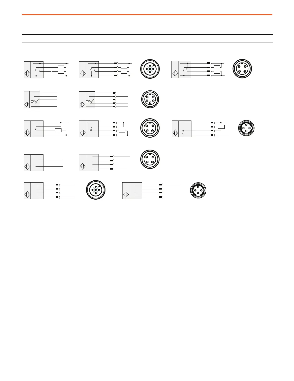
Wiring Diagrams
Figure 1 - Standard and Laser Models
(1) Load can be placed on either black wire to create sourcing or on white wire to create sinking.
IMPORTANT Do not connect an NPN and PNP load simultaneously.
1 Brown
2 White: NPN
4 Black: PNP
3 Blue
2 Red w/White
4 Green No Conn.
3 Red
1 Red w/Black
3 Brown
4 White: NPN
1 Black: PNP
2 Blue
T
T
T T
(+)
( - )
Brown
White: NPN
Black: PNP
Blue
(+)
( - )
Load
Brown
White
Black
Blue
(+) ~
( - )
~
3 Brown
4 White
1 Black
2 Blue
Brown
Orange (C)
Black (NO)
Blue
White (NC)
4 Brown
3 Orange (C)
1 Black (NO)
2 Blue
5 White (NC)
(+)
~
( - )
~
(+)
( - )
Load
Load
Load
Load
Load
(+)
~
( - )
~
Load
(+)
~
( - )
~
(+) ~
( - )
~
4 White
Brown
Blue
(+) ~
( - )
~
3 Brown
1 Black
2 Blue
(+)
~
( - ) ~
Not Used
Not Used
2 White
1 Brown
4 Black
3 Blue
(+)
~
( - )
~
Not Used
Not Used
4 Green
1 Red w/Black
3 Red
2 Red w/White
(+) ~
( - ) ~
Not Used
Not Used
Load
Load
3
2
4
1
3
2
4
1
(1)
(1)
Cable Model: 9_ _0 4-pin DC Micro QD Model: 9_ _0-QD 4-pin DC Mini QD Model: 9_ _0-QD1
Cable Model: 9_ _1, 9_ _2 5-pin AC/DC Mini QD Model: 9_ _1-QD, 9_ _2-QD
Transmitted Beam Source
Cable Model: 42GRL-90_ _
AC/DC Mini QD Model: 42GRL-9_2-QD
DC Micro QD Model: 42GRL-9_0-QD 4-pin DC Micro QD Model: 42GRL-90_3-QD1
Cable Model: 9_ _3 AC/DC Mini QD Model: 9_ _3-QD AC/DC Micro QD Model: 9_ _3-QD1

 Loading...
