PanelView Plus 7 Performance Terminals 3
Rockwell Automation Publication 2711P-PC007A-EN-P - March 2015
Prepare for Panel Mounting
Mounting levers insert into the slots around the bezel to secure the terminal in the panel. The number of mounting levers
varies by terminal size. Each slot has six notches with alignment marks that are locking positions for a mounting lever. The
thickness of the panel that you mount the terminal in determines the locking position required to maintain a NEMA, UL
Type, or IP seal.
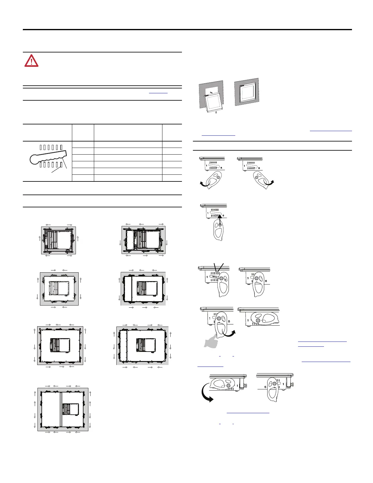
Mounting Lever Orientation and Lock Sequence
Mount the Terminal in a Panel
Follow these steps to mount the terminal in a panel cutout.
1. Use the cutout template shipped with your terminal to mark the cutout dimensions and cut the hole in the panel.
2. Verify the sealing gasket is present on the terminal.
This gasket forms a compression type seal. Do not use sealing compounds.
3. Center the terminal in the panel cutout.
4. Secure the terminal in the panel.
a. Verify the orientation of the mounting levers.
The direction you rotate each mounting lever is different for each terminal size. See Mounting Lever Orientation and
Lock Sequence on page 3.
b. Hold the first mounting lever in the locking sequence vertical to the slot and insert its knob into the large end of the
slot.
c. Slide the mounting lever to a notch that is one or two positions greater than the final locking position for your panel
thickness.
If the final locking position is 3, slide the mounting lever to position 4 or 5.
d. Rotate the mounting lever until its flat side comes in contact with the panel.
e. Repeat steps a
through d for the remaining mounting levers.
5. Adjust each mounting lever to its final position by using the locking sequence in Mounting Lever Orientation and Lock
Sequence on page 3.
a. Unlock mounting lever one in the sequence by rotating it away from the bezel.
b. With the mounting lever positioned vertically to the slot, slide the mounting lever to its final locking position as
determined by the Panel Thickness Range
on page 3.
c. Carefully rotate the mounting lever back toward panel.
d. Repeat steps a
through c to lock the remaining mounting levers in their final position.
ATTENTION:
• Disconnect all electrical power from the panel before making the panel cutout.
• Make sure the area around the panel cutout is clear and that the panel is clean of any debris, oil, or other
chemicals.
• Make sure metal cuttings do not enter any components already installed in the panel and that the edges
of the cutout have no burrs or sharp edges.
• Failure to follow these warnings can result in personal injury or damage to panel components.
Refer to the PanelView Plus 7 Performance Terminals User Manual, publication 2711P-UM008, for
complete installation instructions.
Mounting Slot Mounting
Lever Lock
Position
Panel Thickness Range Typical
Gauge
1 1.50…2.01 mm (0.060…0.079 in.) 16
2 2.03…2.64 mm (0.080…0.104 in.) 14
3 2.67…3.15 mm (0.105…0.124 in.) 12
4 3.17…3.66 mm (0.125…0.144 in.) 10
5 3.68…4.16 mm (0.145…0.164 in.) 8/9
6 4.19…4.80 mm (0.165…0.188 in.) 7
The mounting lever orientations shown are required to maintain NEMA, UL Type, and IP seals. If you
require a NEMA, UL Type, or IP seal, do not use a mounting lever in a different orientation than shown.
1
2
3
4
5
6
Notch
Alignment Mark
ERR
STS
1
2
1
2
5
6
2
7
4
8
8
3
7
5
4
5
3
1
6
42
5
6
8
6
12
8
7
11
5
11
13
9
10
14
12
3
1
6
3
1
1
10
3
7
11
13
9
15
10
16
12
14
2
4
10
1
2
9
4
2
9
8
2
46
82
46
5
317
5
317
6.5-in. Only Touch - 6 Levers 6.5-in. Keypad and Touch - 8 Levers
9-in. and 10.4-in. Only Touch - 8 Levers 10.4-in. Keypad and Touch, 12.1 Only Touch - 10 Levers
15-in. Only Touch - 12 Levers 15-in. Keypad and Touch - 14 Levers
19-in. Only Touch - 16 Levers
Use catalog number 2711P-RMCP mounting levers for PanelView Plus 7 Performance terminals.
The mounting levers for PanelView Plus 7
Performance terminals are black.
Do not use gray mounting levers; they are
not compatible with PanelView Plus 7
Performance terminals.
Use an erasable marker or grease pencil to
mark the alignment marks for visibility of
the slot positions and to mark the final lock
position.
The mounting levers are designed to
break the pin off if they are over torqued.
This helps to prevent damage to the
bezel. If a pin is broken, turn the
mounting lever around and use the other
pin to continue the installation. See
Mounting Lever Orientation and Lock
Sequence on page 3 for restrictions.

 Loading...


