Page 14 of 17 Tech Note for PSA 2012-01-001 PF7000_GEN-95
6. Now, calculate the capacitance from the measured values of test voltage and current. For a good LFC, the calculated
capacitance value for each of the three readings should be within +15% of the LFC nameplate micro-Farad. If it is
outside this range then the LFC must be replaced.
Example: An example is given below to illustrate how the capacitance value is calculated.
e.g. – the LFC under test is rated at 400kVAR, 6600V, 50Hz, 29.2F. You are using 200V, 50Hz test power and have recorded
the values of voltage and current for each test as given in the table below.
Phase – Neutral L1-N L2-N L3-N
Test Voltage 200V 200V 200V
Measured Current 1.87A 1.866A 1.861A
Calculate the capacitance using the first reading. In this case:
V = 200V, I = 1.87 for L1-N
Xc = V/I = 200/1.87 = 106.95
Where f = frequency of the applied voltage.
Similarly, you can calculate the capacitance for the remaining two measurements (L2-N and L3-N).
Answer #3: RESETTING THE “LINE CAP FAILURE” FAULT
Only after testing and confirming the filter capacitors meet the testing criteria and have no visible signs of damage,
can you take the following steps to reset the "Line Cap Failure" fault and clear the Fault Queue.
Resetting the fault allows the VFD to be unlocked and to be able to restart. Clearing the fault queue prevents the "Line Cap
Failure" fault reoccurring on the next VFD powering up, due to "Line Cap Failure" fault still staying in the fault queue.
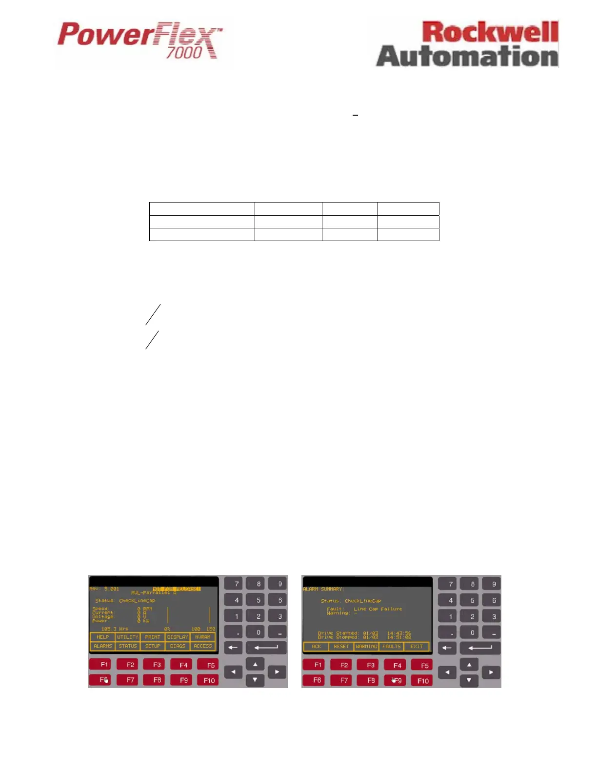
1. From the Main screen, while the flashing messages "CheckDriveInput", “CheckLineCap”, and “DoNotApplyMV”
showing on the STATUS line, press [F6] to get to the Alarm Summary screen (screen shots for reference only –
actual data/detail shown may be slightly different). At the Alarm Summary screen, press [F9] to get to the detailed
Faults screen (refer to Figures 1 and 2).
Figure 1 – Press [F6] to access Alarm screen Figure 2 – Press [F9] to access Fault Queue screen
FC
C
Xcf
C
7.29
95.1065014.32
1
2
1

 Loading...


