2-14
LiquiFlo AC Power Modules, Hardware Reference Version 6.4
Refer to the appropriate board instruction manual for more information. Refer to
section 2.8 of this manual for more information on optional drive kits.
2.6.5 Operator Interface Module Connector
Flat-ribbon connector J7 provides a means of attaching the optional Operator
Interface Module (OIM). The OIM is available for use as a remote keypad for the
LiquiFlo drive. Refer to the OIM instruction manual (D2-3342) for more information.
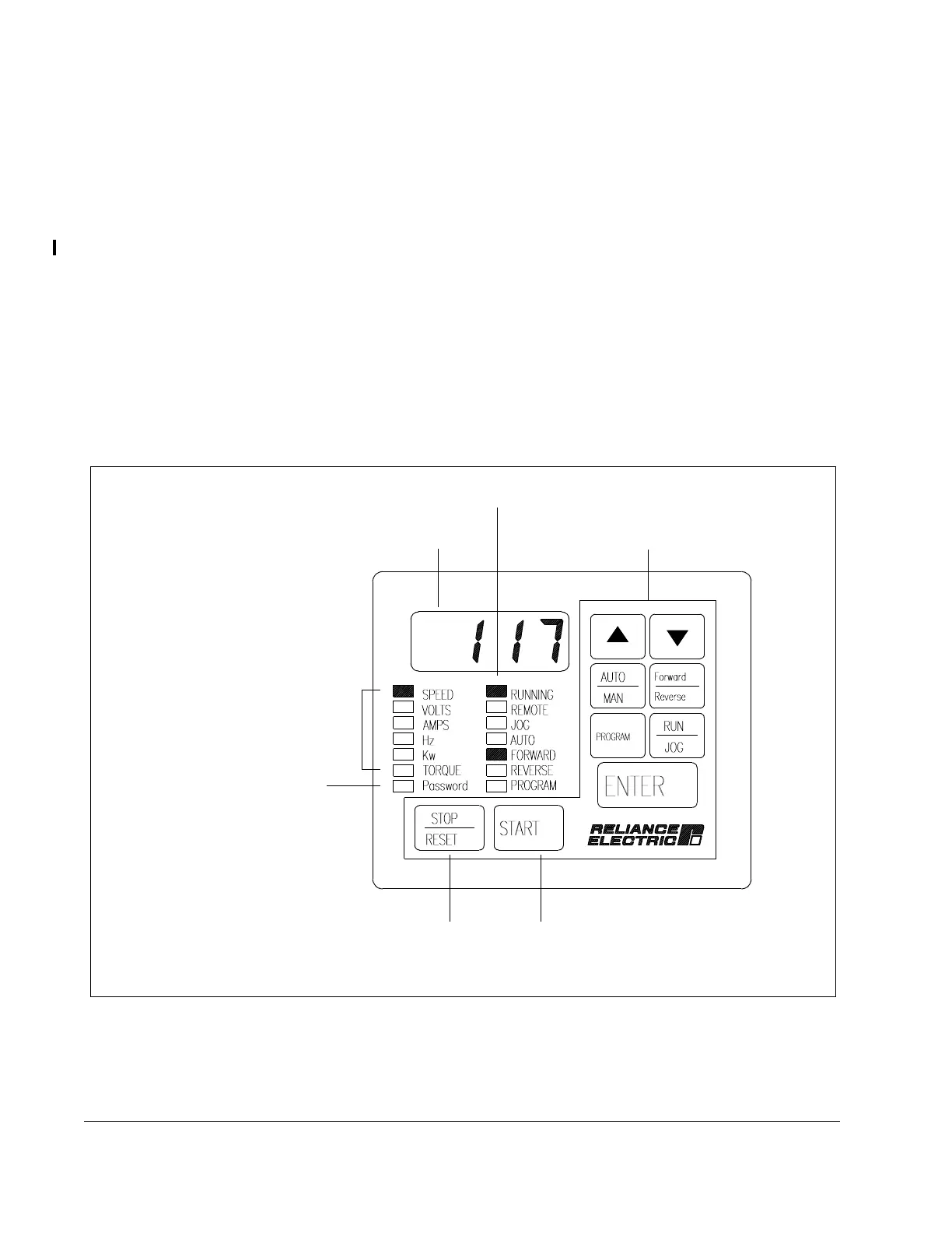
2.6.6 Keypad/Display
The front panel keypad/display is used to program and operate the LiquiFlo drive. See
figure 2.9. The four-character display is used to indicate drive parameters, parameter
values, and fault codes. The fourteen single LEDs indicate drive status and mode, as
well as identifying drive outputs whose values are displayed on the four-character
display.
Refer to the LiquiFlo Software Start-Up and Reference manual for more information.
Figure 2.9 – Keypad/Display
Keypad
Drive Status LEDs
Display
Password LED
Stop/Reset
Key
Start Key
Monitor Mode LEDs
 Loading...


