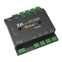
The Z21
is a FLEISCHMANN and ROCO innovation.
31
English
1. The turnout drive connected to output 1 can be operated directly using the default settings: Operating mode 0 (pulse mode).
Terminal 1A is connected using the cable for the branched position and terminal 1B using the cable for the straight position of the
turnout. The precise assignment of the cable colours for the “branch” and “straight” positions depends on the turnout drive in
question and where applicable also on the installation situation. If you would like a shorter or longer switching time on the coil
motor, this can be set for output 1 via CV #3.
2. The electrical decoupling track on output 2 can be operated in operating mode 0 (pulse mode) or also 3 (instantaneous operation).
Only use mode 3 instantaneous operation if you want the same response as for 10775 and you are using a ROCO control centre.
For the decoupling track you can use either terminal 2A or alternatively terminal 2B. This only works to the extent that the decou-
pler is then activated using the command for the “branch” or “straight” turnout position.
3. The ashing light of a level crossing can be operated on output 3 in this example, if it has been congured to operating mode 1
(alternate ash) or 2 (alternate ash with slow fade-up and fade-down, light bulb simulation). The alternate ash is activated using
the “Turnout straight/green” command and deactivated again with the “Turnout branch/red” command. Both the ashing speed
and the brightness can be adjusted in the adjustable frame: For output 3, the ashing speed is set via CV #5 and the brightness is
set via CV #63.
WARNING: Please note that LEDs may generally only be connected to the decoder with a series resistor for current limitation,
regardless of whether they are dimmed or operated at full brightness. The resistance value depends greatly on the LED type
actually used, meaning no accurate data can be provided here. However, commercially available LEDs can normally be operat-
ed with a series resistor of approx. 2.2 - 10 kΩ. If in doubt, start with a higher resistor value.
4. The dual-aspect signal on output 4 is operated in operating mode 4 (continuous operation) or 5 (continuous operation with slow
fade-up and fade-down, bulb simulation). The signal is set to green with the “Turnout straight” command and set to red with the
“Turnout branch” command. The brightness can also be set here in the adjustable frame. On output 4, this is CV #64. The basic
position of the signal when switching on the supply voltage of the switch decoder can be congured via CV #49. Operating modes
4 and 5 cannot be used for light signals, however, but are also used for Street and Building lights on your model railway system.
The corresponding series resistors for the LEDs should also be ensured here. Standard signals often have these already integrated,
but the instructions from the manufacturer in question should be observed.
TIP: Multi-aspect signals can also be operated by combining multiple outputs as appropriate, but we nevertheless recommend
the 10837 Z21 signal DECODER for more complex signals.