The Z21
is a FLEISCHMANN and ROCO innovation.
33
English
6. Conguration
The Z21 switch DECODER can be congured in three different ways:
1. Via the programming button in conguration mode
2. Via POM programming commands
In the interest of ongoing development, we reserve the right to improve and expand the settings and features.
6.1 Conguration via the programming button
To access conguration mode, the button must be pressed for at least 3 seconds until the white “Program” LED begins to ash. Then
release the button again.
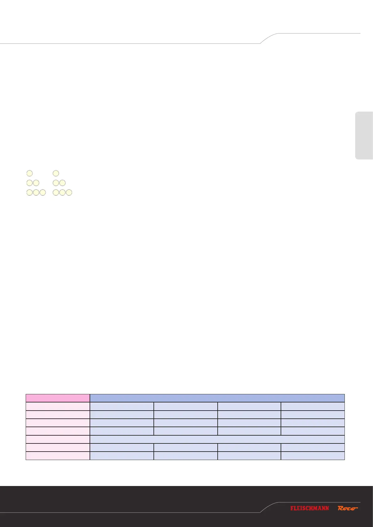
The “Program” LED then displays the currently selected option:
Flashes once in white, option 1: Program addresses for outputs 1 to 8
Flashes twice in white, option 2: Program address for outputs 5 to 8
Flashes three times in white, option 3: Set addressing mode
Press and hold the button again for at least 3 seconds to accept the setting and jump to the next option. This is indicated by the blue
LED lighting up. After accepting the last option, conguration mode is exited and all settings are saved.
6.1.1 Option 1 – Program addresses for outputs 1 to 8
This option is used to program both the rst decoder address for outputs 1 to 4, and the second decoder address for outputs 5 to 8.
1. Keep the programming button held down for at least 3 seconds until the white “Program” LED begins to ash. Then release the
programming button.
The white “Program” LED will then ash normally once (short, pause; short, pause; etc.), and the green LED will be lit continu-
ously.
The switch decoder is then in “Conguration mode, option 1”.
2. Now switch a magnet accessory of your choice.
The magnet accessory can be switched via the Z21 app or another input terminal, such as the multiMAUS.
3. As soon as the switching command has been interpreted by the switch decoder, the new address is applied and conguration
mode is exited automatically. The white LED goes out and the blue LED indicates normal mode.
Die Programmierung der Decoder-Adressen erfolgt gemeinsam für die Ausgänge 1 bis 4 und 5 bis 8 immer in aufsteigenden Vierer-
gruppen. Jede Vierergruppe besteht aus exakt vier aufeinanderfolgende Weichennummern, beginnend mit 1 bis 4, 5 bis 8, 9 bis 12, 13
bis 16, et cetera. Die letzte programmierbare Vierergruppe reicht von 2037 bis 2040.
Decoder address Turnout numbers (group of four)
1 1 2 3 4
2 5 6 7 8
3 9 10 11 12
4 13 14 15 16
… …
509 2033 2034 2035 2036
510 2037 2038 2039 2040