WWW.Z21.EU
Model Railway Control Unit
30
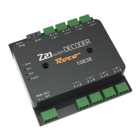
Switching power supply:
Voltage: 12 – 20 V DC
Output current: min. 2 A
Before rst use, the switch decoder must be programmed so that it knows which decoder addresses and switch numbers to respond
to. If you are operating the Z21 switch DECODER on a control centre from another manufacturer, please observe the information in
Operation on control centres from other manufacturers.
The procedure for programming the decoder addresses using the programming button is explained in detail in the Option 1 – Program
addresses for outputs 1 to 8.
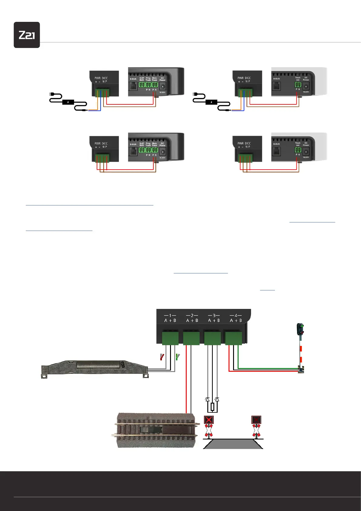
The consumers, such as coil motors etc, are connected to outputs 1 to 8. In the centre, the “+” terminal refers to the common plus pole
in each case. The “A” terminal corresponds to the “branch / red” position, and the “B” terminal to the “straight / green” position. Each
of the 8 outputs can be set as necessary via CV #41 to #48 to an individual operating mode. This can be congured either via the zLink
or via “POM” programming on the main track, see also section Conguration via POM.
More information on the comprehensive conguration options of the outputs can be found in section CV list. Given here are just a few
examples for common applications: