EN
43
7.3 TEST mode
8LI8)78QSHIMWYWIHXSXIWXEGXMZEXMSRSJXLIGSQQERHWERHWEJIX]HIZMGIW[MXLZMWYEPGSRƼVQEXMSR
To activate the mode, press the TEST button with the automatic gate system at rest. If the gate is moving, pressing
TEST stops the gate. Pressing the button again enables TEST mode.
-JXLIƽEWLMRKPMKLXERHXLIKEXISTIRMRHMGEXSVPEQTMPPYQMREXIJSVSRIWIGSRHIEGLXMQIEGSRXVSPMWYWIHSVEWEJIX]
device is activated.
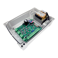
8LIGSQQERHWMKREPWXEXYWMWWLS[RSRXLIPIJXLERHWMHISJXLIHMWTPE]JSVWIGSRHW320=[LIRXLIVIWTIGXMZI
GSQQERHWMKREPMWEGXMZI%4',444)36*SVI\EQTPIMJXLIKEXISTIRGSQQERHMWEGXMZEXIHXLIPIXXIVW%4
appear on the display.
8LIWXEXYWSJXLIWEJIX]HIZMGIWMRTYXWMWWLS[RSRXLIVMKLXLERHWMHISJXLIHMWTPE]8LIRYQFIVSJXLIXIVQMREP
VIPEXMZIXSXLIWEJIX]HIZMGIMREPEVQWXEXIƽEWLIW
Example: STOP contact in alarm state.
No safety device in alarm state, and no limit switch activated
STOP.
Sensing edge COS1.
Sensing edge COS2.
Photocell FT1.
Photocell FT2.
Gate open limit switch13836&,SerieMJIREFPIH).
Gate open limit switch13836&,7IVMIMJIREFPIH).
NOTE: If one or more contacts are open, the gate will not open or close. This does not apply for the limit switch signal
state, however, which is shown on the display but does not prevent normal operation of the gate.
-JQSVIXLERSRIWEJIX]HIZMGIMWMREPEVQWXEXISRGIXLITVSFPIQVIPEXMZIXSXLIƼVWXHIZMGIMWVIWSPZIHXLIEPEVQJSV
the next device is displayed. Any further alarm states are also displayed with the same logic.
Press the TEST button again to exit test mode.
After 10 seconds with no user input, the display returns to command and safety device state display mode.
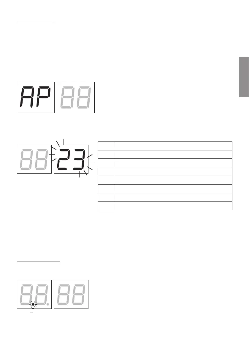
7.4 Standby mode
8LMWQSHIMWEGXMZEXIHEJXIVQMRYXIW[MXLRSYWIVMRTYX8LI43;)60)(ƽEWLIWWPS[P]
Press UP a, DOWN b,
+
, - to reactivate the control unit.
POWER