EasyManua.ls Logo

Roger MC16 - Page 6

Roger MC16
14 pages
Print Icon
To Next Page IconTo Next Page
To Previous Page IconTo Previous Page
Loading...
MC16 Installation Manual.doc 2018-11-22
6/14
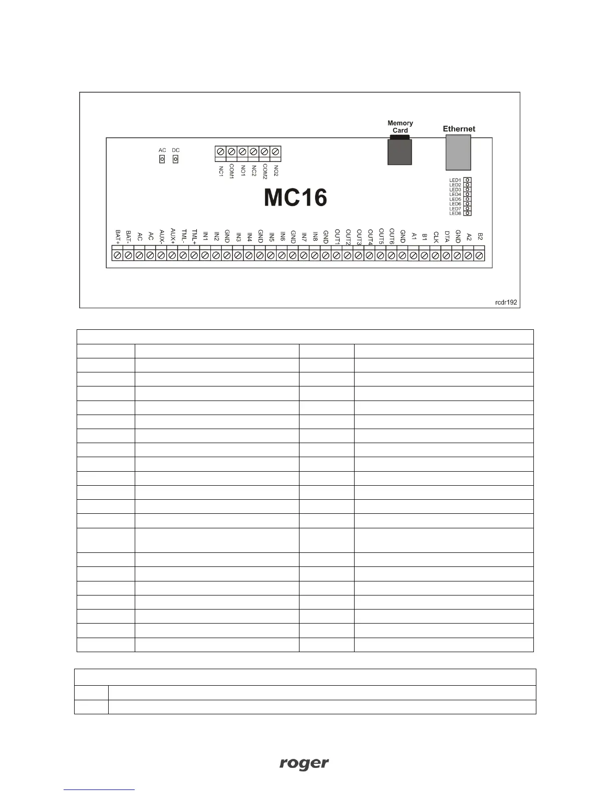
MC16 ELECTRONIC MODULE VIEW
Fig. 3 MC16 board view.
Table 1: MC16 Connection Terminals
Terminal
Description
Terminal
Description
NC1
REL1/ NC contact
IN5
IN5 input
COM1
REL1/ COMM contact
IN6
IN6 input
NO1
REL1/NO contact
GND
Signal ground
NC2
REL2/NO contact
IN7
IN7 input
COM2
REL2/COMM contact
IN8
IN8 input
NO2
REL2/NO contact
GND
Signal ground
BAT+
Backup battery plus node
OUT1
OUT1 transistor output
BAT-
Backup battery minus node
OUT2
OUT2 transistor output
AC
AC supply input
OUT3
OUT3 transistor output
AC
AC supply input
OUT4
OUT4 transistor output
AUX-
12VDC/1A supply output, minus node
OUT5
OUT5 transistor output
AUX+
12VDC/1A supply output, plus node
OUT6
OUT6 transistor output
TML-
12VDC/0.2A supply output, minus
node
GND
Signal ground
TML+
12VDC/0.2A supply output, plus node
A1
RS485(1)/ Line A
IN1
IN1 input
B1
RS485(1)/ Line B
IN2
IN2 input
CLK
RACS CLK/DTA Line CLK
GND
Signal ground
DTA
RACS CLK/DTA Line DTA
IN3
IN3 input
GND
Signal ground
IN4
IN4 input
A2
RS485(2)/ Line A (not used)
GND
Signal ground
B2
RS485(2)/ Line B (not used)
LED
Function
AC
AC supply available

Other manuals for Roger MC16

Related product manuals