Operation
R&S
®
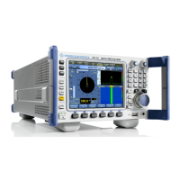
DDF205
34Getting Started 4073.0187.02 ─ 03
2.
Press "DF"
to switch the R&S DDF205 to DF mode. The panel layout will change
to the default direction finding layout with focus on DF IF Panel. Follow the steps
as explained in chapter 2.3.2.4, "Settings – Receiver and Antenna",
on page 23 to confirm that your DF antenna is installed properly and recognized
by the system.
3. Use the main ROTARY KNOB or the numeric keypad to select the frequency
for which you want to conduct direction finding as explained in chapter 2.3.2.5,
"Basic Operation - Fixed Frequency Mode (FFM)", on page 25. Switch to DF
mode.
4. Choose an appropriate combination of "SPAN", "STEP" and "selectivity" in order
to optimize the direction finding bandwidth so that it matches the channel spac-
ing of the RF band that is being monitored.
5. Also, choose a sufficiently small DF measurement time so that the measurement
can take place within a short time-frame (this is in particular important when the
observation is done on a moving vehicle).
In case the measurement takes place on a stationary system, use the built-in
compass to configure North Correction, as explained in "DF Antenna and Com-
pass Setup" on page 32. Alternatively use a standalone compass and manually
key-in the North Correction.
6. Use the PANEL key to change the focus to the Polar Panel
7. Set the DF Quality threshold to a value reasonably high so that reliable DF
measurement can be achieved for the channel that is being investigated.
8. Now the direction finding will most likely produce reliable bearing results, visible
by the stationary position of the yellow bearing arrow in the wind rose. The
heading indicator (white-color vane) in the wind rose corresponds with the com-
pass value.
2.3.2.7 Advanced Operation – FSCAN (Frequency Scan)
Frequency scan allows the monitoring of a frequency span greater than the real-
time IF spectrum bandwidth.
Graphical User Interface (GUI)
 Loading...