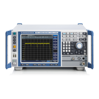
The R&S FSL is a spectrum analyzer designed for a variety of measurement tasks, ranging from basic signal analysis to advanced applications in industrial and laboratory environments. It is available in several models: R&S FSL3 (1300.2502K03, 1300.2502K13), R&S FSL6 (1300.2502K06, 1300.2502K16), and R&S FSL18 (1300.2502K18, 1300.2502K28). The device is built and tested according to EC Certificate of Conformity and safety standards, emphasizing continuous monitoring through a quality assurance system.
Function Description
The R&S FSL serves as a spectrum analyzer, capable of measuring the level and frequency of signals, harmonics, signal spectra with multiple signals, modulation depth of AM-modulated carriers, and power characteristics of burst signals in zero span. It also supports measurements of signal-to-noise ratio for burst signals and FM-modulated signals. The instrument can be operated in standalone mode or integrated into a rack.
Key functions are accessed via a front panel with dedicated keys and a rotary knob. These include:
- ON/STANDBY: Switches the instrument on and off, with standby mode available when connected to AC power.
- PRESET: Resets the instrument to its default state.
- FILE: Manages stored instrument settings and files.
- SETUP: Provides basic configuration functions such as frequency reference (external/internal), noise source, video/IF output (optional), transducer factors, date, time, display configuration, LAN interface, remote control (optional GPIB), self-alignment, firmware update, option enabling, and service support functions.
- PRINT: Customizes printouts and configures the printer.
- HELP: Displays the Online Help system.
- MODE: Selects between measurement modes and firmware options.
- MENU: Jumps to the highest softkey menu level.
- FREQ: Sets center, start, and stop frequencies, frequency offset, and signal track function.
- SPAN: Sets the frequency range to be analyzed.
- AMPT: Sets reference level, dynamic range, RF attenuation, level display unit, level offset, input impedance, and activates the preamplifier (optional).
- BW: Sets resolution and video bandwidth.
- SWEEP: Sets sweep time and measurement points, and selects continuous or single measurement.
- TRIG: Sets trigger mode, threshold, delay, and gate configuration (optional).
- MKR: Sets and positions absolute and relative measurement markers, including functions like frequency counter, noise marker, phase noise marker, fixed reference point, n dB down function, AF demodulation, and marker list.
- MKR->: Used for marker search functions (max/min of trace), assigns marker frequency to center frequency, marker level to reference level, and restricts search area.
- RUN: Starts a new measurement.
- MEAS: Performs advanced measurements such as time domain power, channel/adjacent channel/multicarrier adjacent channel power, occupied bandwidth, signal statistics (APD, CCDF), carrier-to-noise spacing, AM modulation depth, third-order intercept point (TOI), and harmonics.
- LINES: Configures display lines and limit lines.
- TRACE: Configures measured data acquisition and analysis.
The instrument's display area provides information on hardware settings (Ref, Offset, Att, RBW, VBW, SWT), status (UNCAL, OVLD, IFOVL, LOUNL, ExtRef, OVEN), trace information (Trace #, Detector, Trace Mode), and enhancement labels (BAT, DC, Ext, Sgl, Trg, Vid, Frq, Tdf, PA, NCor, GAT, 75Ω, Pwr Max).
Important Technical Specifications
- Operating Conditions: Designed for indoor use, max. operating altitude 2000 m, max. transport altitude 4500 m. IP protection 2X.
- Power Supply: Operates from AC power (±10% nominal voltage, ±5% nominal frequency, overvoltage category 2, pollution degree 2). Can be optionally fitted with a DC power supply connector (R&S FSL-B30) or a NiMH battery pack (R&S FSL-B31). Priority scheme for power supply: AC > DC > battery.
- RF Input: 50Ω, AC-coupled. Max input DC voltage 50 V (for models ≤ 6 GHz) or 25 V (for models > 6 GHz with attenuation < 10 dB). Max continuous power at RF input 30 dBm (1 W) for models ≤ 6 GHz, 20 dBm for models > 6 GHz with attenuation < 10 dB, and 30 dBm for models > 6 GHz with attenuation ≥ 10 dB.
- Tracking Generator Output (GEN OUTPUT 50Ω): Available on R&S FSL models 13, 16, and 28. Max reverse power 1 W or 50 V DC.
- Interfaces:
- USB: Two female connectors on the front panel for keyboard, mouse, memory stick, or power sensor (via adapter cable R&S NRP-Z4). USB cables should not exceed 1m.
- AF OUT: Miniature jack plug for headphones.
- LAN: RJ-45 connector for remote control, printouts, and data transfer. Supports twisted-pair category 5 UTP/STP cables.
- EXT TRIGGER / GATE IN: Female connector for external TTL trigger/gate input (low <0.7 V; high >1.4 V), 10 kΩ impedance.
- EXT REF: Input for 10 MHz reference signal (≥ 0 dBm). With OCXO option (R&S FSL-B4), can also be an output.
- MONITOR (DVI-D): Female DVI-D connector for external monitor. On newer instruments, this is replaced by a VGA connector. Standard for R&S FSL18, optional for R&S FSL3 and FSL6 depending on serial number.
- POWER SENSOR (optional R&S FSL-B5): LEMOSA female connector for R&S NRP-Zxy power sensors.
- NOISE SOURCE CONTROL (optional R&S FSL-B5): Female connector for +28 V / 0 V supply voltage for external noise sources (max 100 mA).
- IF/VIDEO OUT (optional R&S FSL-B5): Female BNC connector for 20 MHz IF output or video output.
- AUX PORT (optional R&S FSL-B5): 9-pole SUB-D male connector for TTL control signals (max 5 V).
- GPIB interface (optional R&S FSL-B10): IEEE488 and SCPI compliant for remote control. Default address 20.
- LXI Compliance: R&S FSL complies with LXI class C, offering Ethernet LAN interface, web server, VXI-11 protocol, and IVI instrument driver. Requires Windows XP Service Pack 2.
Usage Features
- User Interface: Intuitive operation via front panel keys, rotary knob, and softkeys. Dialog boxes are used for parameter entry, supporting numeric and alphanumeric input.
- Help System: Context-sensitive and non-context-sensitive help available via the HELP key, with tabs for Contents, View, Index, and Zoom.
- Display Customization: Screen colors can be adjusted using predefined color sets or user-defined colors for various display objects.
- Automatic Display Off: Feature to automatically switch off the screen after a user-defined period of inactivity to save power.
- Printer Configuration: Supports local USB printers and network printers. Printouts can be configured for color, black-and-white, and output format (image file, clipboard, printer).
- External Monitor Support: Can connect to an external monitor via DVI-D or VGA. Simultaneous display on both internal and external screens is possible.
- USB Device Support: Plug & play installation for various USB devices like memory sticks, CD-ROM drives, keyboards, and mice.
- Remote Control: Supports remote operation via LAN (LXI Browser Interface) and optional GPIB interface. Programming examples are provided for Visual Basic.
- Instrument Modes: "On" mode (ready for operation, green LED), "Standby" mode (parts active, yellow LED, rapid resume), and "Off" mode (completely off, no LEDs).
- Self-Alignment and Self-Test: Functional tests to ensure proper operation and system correction, recommended after warm-up.
- Firmware Update: Can be updated via USB devices, GPIB, or LAN, with options to activate firmware features using license keys.
- Automatic Loading: Instrument settings can be configured to load automatically during booting or preset.
Maintenance Features
- Cleaning: The instrument's exterior should be cleaned with a soft, lint-free dust cloth. Avoid chemical cleaning agents like solvents, thinners, acetone, acids, or bases. Ensure air vents are not obstructed.
- Fuse Replacement: Protected by two IEC 127 – T 3.15 H / 250 V fuses located on the rear panel. Replacement requires disconnecting from power supply.
- Battery Charging: The optional NiMH battery pack (R&S FSL-B31) can be charged via AC or DC power supply, either within the instrument or externally using a dedicated power supply unit (R&S FSL-Z4). Charging duration varies (e.g., 5h in standby, 9h when switched on).
- Software Updates: Windows XP service packs and instrument software updates should only be installed if approved by Rohde & Schwarz to prevent malfunctions.
- Calibration: Recommended calibration interval information is available in the R&S FSL data sheet.
- Packaging: Retain original packaging for safe transport or shipment to ensure warranty claims are accepted.
- Safety: Basic safety instructions emphasize proper use, skilled personnel, and adherence to electrical safety, operating conditions, and handling heavy equipment. Safety labels on the product indicate various risks and warnings.