Page 6 of 16 Level: 10/2020
Enjoy your results
5. START-UP
5.1. Delivery / Unpacking of kiln
The ROHDE Toploader will usually be delivered on a pallet by a freight-forwarding agent� Immediately after delivery
check the packaging for any visible damage� Should you detect any damage, unpack the pallet together with the
driver and check the goods again for damage� If you detect any damage please enter details on the delivery note
and let the driver countersign your remarks� Keep one copy of the complaint for yourself� Inform the freight-forwarding
agency immediately of the damage� Complaints submitted at a later date cannot be taken into consideration�
5.2. Disposal of packing material
Contribute to a clean environment by disposing of wood, cardboard and plastic packaging material in your nearest
waste disposal plant� For further information concerning the disposal of packaging material please contact your
dealer or community council�
5.3. Installation environment / Location
When selecting a suitable place for your kiln, please note the following guidelines and prepare the kiln environment
accordingly:
• Place the kiln on an even surface�
• The distance to the walls should be at least 25 cm on each side�
• The floor, ceiling insulation, walls, dividing walls, panelling, etc� must be made of flame resistant material�
• Make sure that the kiln environment can be properly ventilated� Otherwise a ventilation system must be installed�
Please consult a qualified ventilation specialist to find out whether a ventilation system is necessary�
5.4. Assembly of kiln
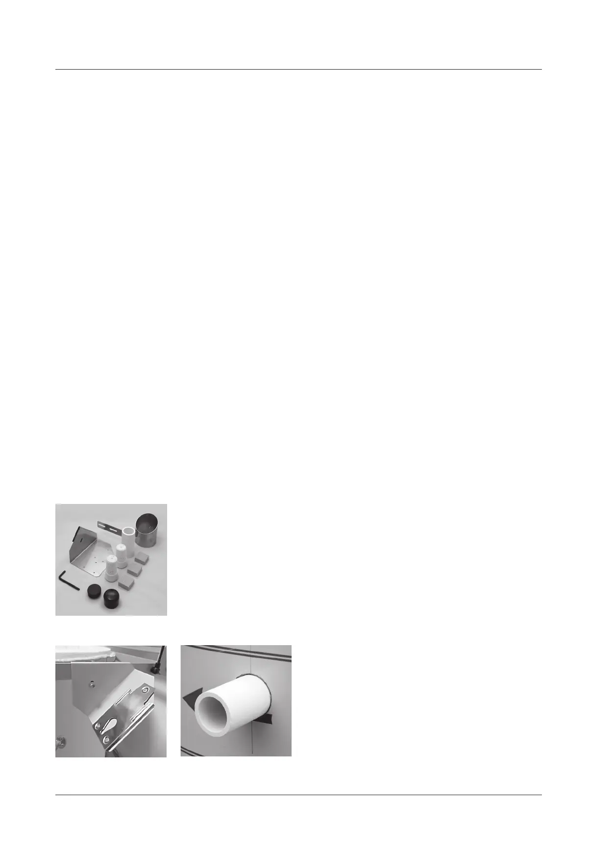
Check the enclosed accessories first (figure 1):
• 3 cordierite blocks (6 blocks for TE 165/250 and TE 300)
• 1 ceramic tube for exhaust air
• 2 sealing plugs
• 1 plastic cap for kiln stand
• 1 spare part for kiln stand
• 1 exhaust air socket and fixing screws
• 1 panel for mounting the controller and fixing screws (not shown)
You will also find enclosed the controller as well as two
instruction manuals for the controller and the kiln� First
screw the mounting panel (figure 2) into the holes indi-
cated on the cover bolt (obey the enclosed assembly
instructions)�
Take the ceramic tube out of the box and plug it onto the
exhaust air opening on the left side of the kiln (figure 3)�
figure 2
figure 1
figure 3


 To Next Page