10/36
© 2022 ROHM Co., Ltd.
65UG018E Rev.001
July 2022
User’s Guide
indicates correct FPGA start-up.
7. When the onboard NOR flash memory is programmed with the default software, the red LED501 flashes and red LED502
lights up.
Alternatively, steps 4 and 5 could also be applied before step 3. In this case, the EVK will start up as soon as a 12-24V DC supply
voltage is connected.
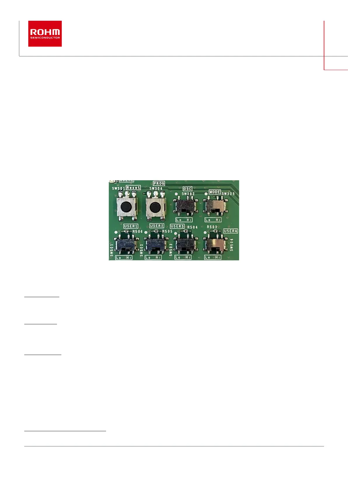
3.6. Onboard switches
The Spartan-7 PMIC EVK contains two onboard pushbuttons and 6 onboard switches. 4 of the switches are free of use to be pro-
grammed as input signal for an FPGA input port.
Figure 4: top: two system pushbuttons and two system switches; bottom: 4 user switches
The system buttons and switches SW301 to SW304 have the following functions:
SW301 (Reset): system reset pushbutton.
Pushing this button resets and restarts the system.
SW302 (OSC): oscillator activation switch. Default = High.
Low = output of oscillator is high impedance. High = oscillator provides specified frequency output (200MHz).
SW303 (MODE): configuration mode switch. Default = Low.
This switch is connected to one of the 3 mode input pins M[2:0] of the Spartan-7 FPGA. Pin0 is hard-wired to High level, pin1 is
hard-wired to Low level and pin2 can be set to either level via SW303. Hence, available configurations of M[2:0] are “001” (= Master
SPI, SW303 is in position “Low”) and “101” (= JTAG, SW303 is in position “High”):1
1
See “7 Series FPGAs Configuration User Guide”, UG470