11/36
© 2022 ROHM Co., Ltd.
65UG018E Rev.001
July 2022
User’s Guide
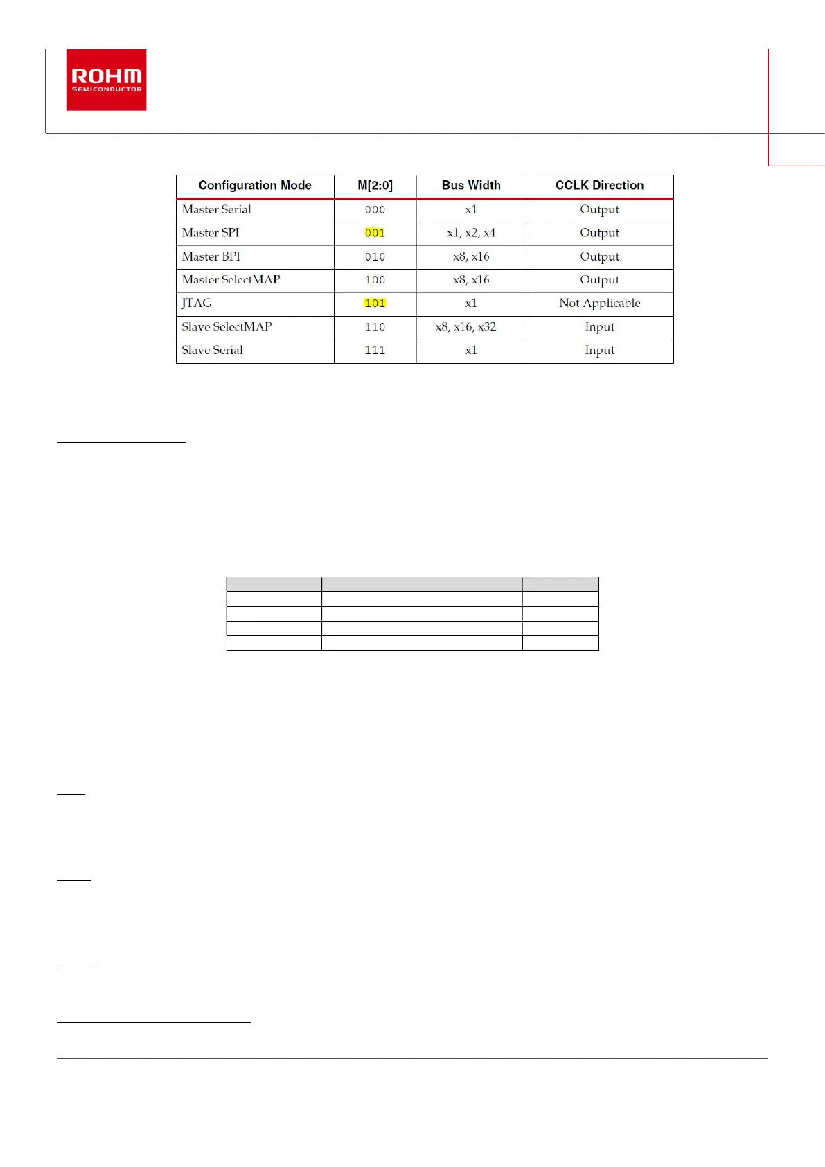
Table 2: Configuration modes set by MODE switch (SW303)
SW304 (PROGRAM_B):
when pushbutton SW304 is pressed, the FPGA configuration is cleared, and a new configuration sequence is initiated.
2
The 4 user switches SW501 to SW504 set their assigned Spartan-7 FPGA input pin (see Table 3 below) either to High-level or Low-
level. The user can integrate the switches in own Spartan-7 software developments. They are wired to the following input ports of the
Spartan-7 XC7S50 FPGA:
SW501 IO_L13P_T2_MRCC_15 F14
SW502 IO_L12N_T1_MRCC_15 D15
SW504 IO_L11N_T1_MRCC_15 C18
Table 3: input pin assignment for user switches
3.7. PMIC status pins
The PMIC BD96801 has some status output pins that can be connected to free input pins of the Spartan-7 FPGA:
INTB: this open drain pin is asserted to low level when PMIC indicates a warning. It can be connected to pin F15 of the FPGA by
inserting the 0R resistor R563. Make sure that you program the FPGA such that pin F15 is high impedance or high-level during start
up. R563 is not mounted on board (default).
ERRB: this open drain pin is asserted to low level when PMIC indicates an error. It can be connected to pin G15 of the FPGA by
inserting the 0R resistor R564. Make sure that you program the FPGA such that pin F15 is high impedance or high-level during start
up. R564 is not mounted on board (default).
PRSTB: this open drain pin is an open drain reset signal for SoC or FPGA. It can be connected to pin G17 of the FPGA by inserting
the 0R resistor R565. Make sure that you program the FPGA such that pin F15 is high impedance or high-level during start up. PRSTB
2
See “7 Series FPGAs Configuration User Guide”, UG470