Do you have a question about the Roland Aerophone AE-10 and is the answer not in the manual?
User data may be lost during procedures. Back up and restore.
Guidelines for replacing components near heat/power circuits.
Explains why some parts are not supplied as service parts.
Explains abbreviations like "NIU" and "UnPop".
Details for sending problem reports under warranty.
Key layout, sound generator, memory, effects, controllers.
Connectors, power supply, and battery life.
Dimensions and weight of the unit.
List of included and separately sold items.
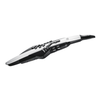
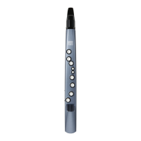
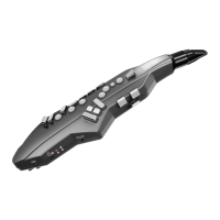
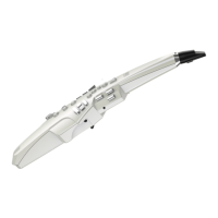
Lists and describes the numbered controls on the unit.
Visual representation of internal components.
Links to detailed exploded views (Fig. A, B).
Parts list for the top section.
Parts list for main and sensor boards.
Parts list for various internal parts like keys, switches, etc.
Parts list for the mouthpiece assembly.
Detailed view and parts list for View 1.
Detailed view and parts list for Views 2 & 3.
Detailed view and parts list for Views 4 & 5.
Detailed view and parts list for Views 6 & 7.
Detailed diagram and parts list for Exploded View Fig. A.
Parts for the panel sheet assembly and its sub-boards.
Detailed diagram and parts list for Exploded View Fig. B.
Parts for panel sheet and sub-boards referenced in Fig. B.
Detailed steps for taking the unit apart.
Guidelines for routing wires during assembly.
Precautions for installing keys correctly.
Steps to install the rubber switch and center panel.
Steps for installing rubber cap and tube silicone.
How to check the Sus Bar for bends.
Steps for assembling the bottom and top cases.
Procedure for installing the mouthpiece assembly.
Steps for connecting the tube to the sensor board.
Visual representation of internal wiring connections.
High-level diagram of the unit's functional blocks.
Steps to perform a factory reset.
Instructions for updating the unit's firmware.
Introduction to test modes and list of available tests.
Checks software version and breath sensor.
Verifies power supply connections and voltage.
Tests Digital Signal Processor and switch operations.
Tests audio output and USB connectivity.
Tests headphones, controller, display, ROM, and bite sensor.
Adjusts bite sensor and performs factory test.
Tests auto-off and battery performance.
Circuit diagrams for the CPU and reset functions.
Circuit diagrams for memory and I/O.
Circuit diagrams for ARP-CTR and system mode.
Circuit diagrams for octave switches.
Circuit diagrams for audio processing and muting.
Circuit diagram for the MPX block.
Circuit diagram of the power supply section.
Circuit diagrams for breath and bite sensor controls.
Top view of the panel sheet assembly and its boards.
Circuit diagram for carbon contact switches.
Circuit diagram for Side-L panel connections.
Circuit diagram for Side-R panel connections.
Circuit diagram for the connect board.
Circuit diagram for the phones board.
Paper template for checking Sus Bar straightness.
| Key layout | Saxophone type |
|---|---|
| Breath sensor | Yes |
| Product color | White |
| Sound effects | Chorus, Reverberation |
| RMS rated power | 3 W |
| Speaker diameter | 28 mm |
| Number of built-in speakers | 2 |
| 6.35 mm (1⁄4-inch) input | 1 |
| Battery type | AA |
| Operating time | 7 h |
| Battery capacity | 1900 mAh |
| Power source type | Battery |
| Battery technology | Nickel-Metal Hydride (NiMH) |
| Number of batteries supported | 6 |
| Display type | LCD |
| Depth | 93 mm |
|---|---|
| Width | 128 mm |
| Height | 574 mm |
| Weight (including battery) | 855 g |